Laser rangefinder correction method

A technology of a laser range finder and a calibration method, applied in the field of measuring instruments, can solve the problems of inaccurate distance measurement, amplitude and phase errors, etc.

Active Publication Date: 2016-11-23
WUHAN HI TARGET DIGITAL CLOUD TECH CO LTD
View PDF2 Cites 22 Cited by
  • Summary
  • Abstract
  • Description
  • Claims
  • Application Information

AI Technical Summary

Problems solved by technology

[0005] The inventor found in the research that the zero-crossing detection method in the prior art, due to the nonlinear characteristics of the signal amplification link, makes th

Method used


Image

  • Laser rangefinder correction method
  • Laser rangefinder correction method
  • Laser rangefinder correction method

Examples


Embodiment Construction

[0059] In order to make the purpose, technical solutions and advantages of the embodiments of the present invention clearer, the technical solutions in the embodiments of the present invention will be clearly and completely described below in conjunction with the drawings in the embodiments of the present invention. Obviously, the described embodiments are only It is a part of embodiments of the present invention, but not all embodiments. The components of the embodiments of the invention generally described and illustrated in the figures herein may be arranged and designed in a variety of different configurations. Accordingly, the following detailed description of the embodiments of the invention provided in the accompanying drawings is not intended to limit the scope of the claimed invention, but merely represents selected embodiments of the invention. Based on the embodiments of the present invention, all other embodiments obtained by those skilled in the art without making...


PUM


Abstract

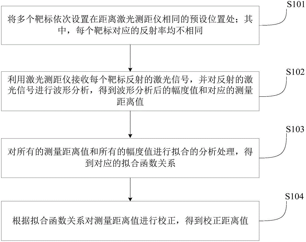
The invention provides a laser rangefinder correction method, the method comprises the steps: a plurality targets are arranged on a preset position with the same distance in sequence; wherein reflectivities corresponding to every targets are different; a laser rangefinder is utilized to receive a laser signal reflected by each target and performs waveform analysis on reflected laser signals, so that amplitude values and corresponding measuring distance values are obtained; fitting analyzing and processing are performed on all measuring distance values and amplitude values, and corresponding fitting function relations are obtained; the measuring distance values are corrected according to the fitting function relations, corrected distance values are obtained, according to the above steps, an amplitude-phase error because of different reflectivities is minimized, so that the precision of distance measurement is improved.

Description

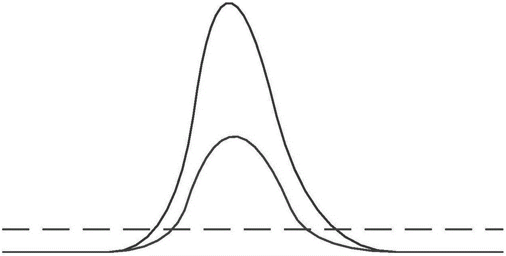
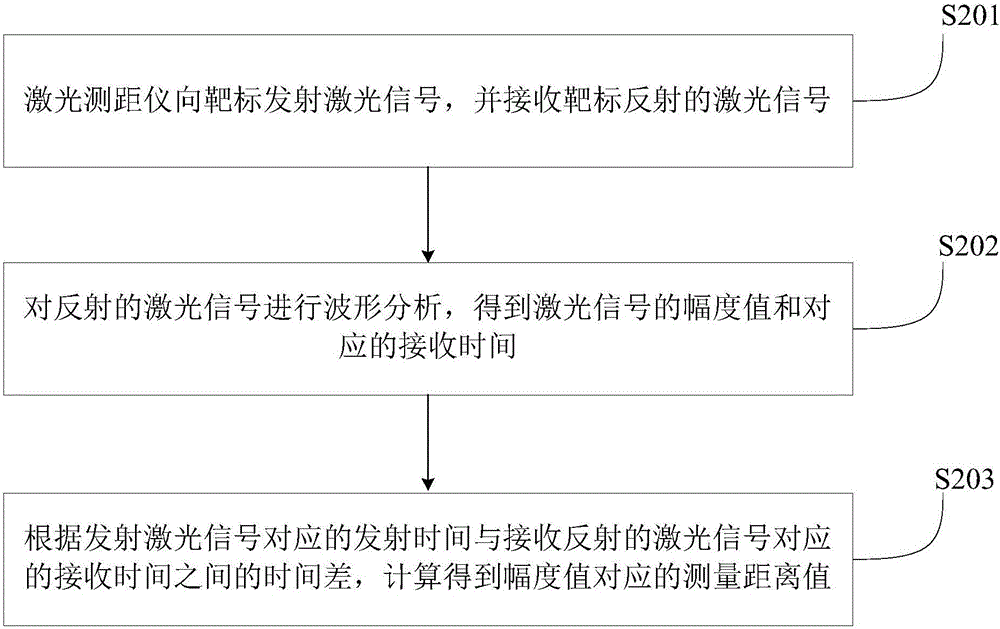
technical field [0001] The invention relates to the technical field of measuring instruments, in particular to a calibration method for a laser range finder. Background technique [0002] The laser range finder is an instrument that uses a certain parameter of the modulated laser to accurately measure the distance of the target. As a common laser rangefinder, the pulsed laser rangefinder emits a beam or a sequence of short pulse laser beams to the target when it is working, and the photoelectric element receives the laser beam reflected by the target, and the timer measures the laser beam from The time from transmission to reception calculates the distance from the observer to the target. For the convenience of the following description, record the transmission time as T1 and the reception time as T2. [0003] However, since the reflectivity of different targets is not the same, the intensity of the return light signal generated by targets of different materials at a speci...

Claims


Application Information

Patent Timeline
IPC IPC(8): G01S17/08G01S7/497
CPCG01S7/497G01S17/08
Inventor 余建伟符运强翁国康胡庆武陈小宇毛庆洲刘守军陆晓明杨晶
Owner WUHAN HI TARGET DIGITAL CLOUD TECH CO LTD
Why Eureka
Try Eureka