System and method for imaging and illumination for cell confluence measurement

a cell confluence and imaging technology, applied in the laboratory field, to achieve the effect of minimizing space and minimizing spa

Active Publication Date: 2022-04-21
CORNING INC
View PDF14 Cites 0 Cited by
  • Summary
  • Abstract
  • Description
  • Claims
  • Application Information

AI Technical Summary

Benefits of technology

[0008]Disclosed herein is a system and method for imaging cells in trays with illumination and imaging systems that sit side-by-side but still allow for back illumination of the cells. The imaging and illumination system is compact and functional and can be used with cell growth trays.
[0011]Integrating the invention into a stand-alone monitoring plate can allow the use of the system with industry standard cell culturing vessels. The invention has an advantage because the illumination system and the imaging system are next to each other and, as such, can be installed as a monolithic apparatus. They can be pre-aligned to each other and take up minimal space in the cell growth trays. Any space taken up by a camera system is space that cannot be used for cell growth. This minimizes the space and creates an image of the cells by rear illumination.

Problems solved by technology

Any space taken up by a camera system is space that cannot be used for cell growth.

Method used


Image

  • System and method for imaging and illumination for cell confluence measurement
  • System and method for imaging and illumination for cell confluence measurement
  • System and method for imaging and illumination for cell confluence measurement

Examples


Embodiment Construction

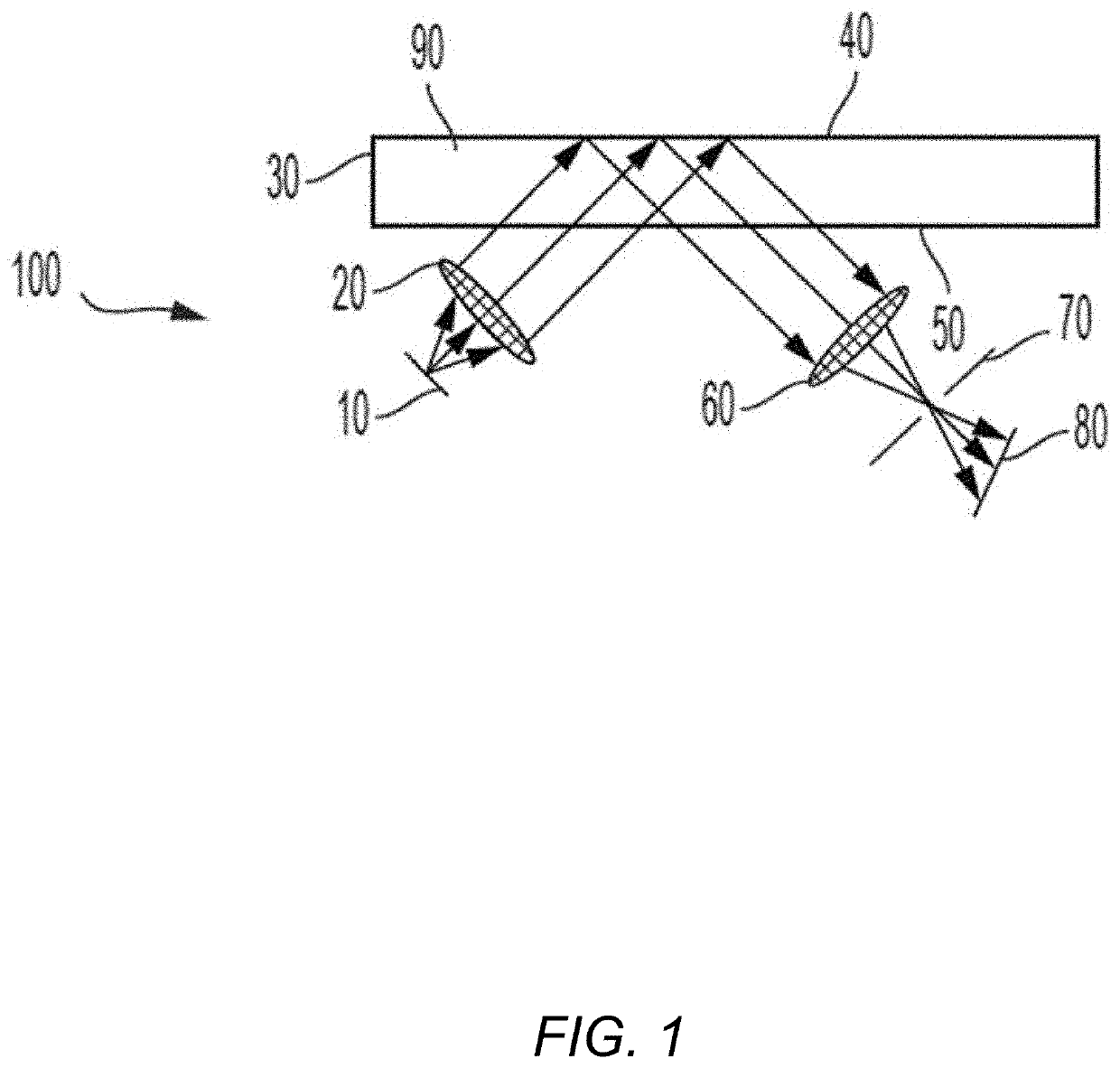
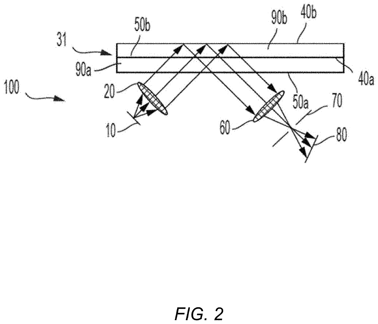
[0031]Reference will now be made in detail to the present embodiment(s), an example(s) of which is / are illustrated in the accompanying drawings. Whenever possible, the same reference numerals will be used throughout the drawings to refer to the same or like parts.

[0032]All scientific and technical terms used herein have meanings commonly used in the art unless otherwise specified. Any definitions provided herein are to facilitate understanding of certain terms used frequently herein and are not meant to limit the scope of the present disclosure.

[0033]The present disclosure is described below, at first generally, then in detail on the basis of several exemplary embodiments. The features shown in combination with one another in the individual exemplary embodiments do not all have to be realized. In particular, individual features may also be omitted or combined in some other way with other features shown of the same exemplary embodiment or else of other exemplary embodiments.

[0034]The...


PUM

PropertyMeasurementUnit
oblique angleaaaaaaaaaa
focal lengthaaaaaaaaaa
microscopic structuresaaaaaaaaaa

Abstract

A cell monitoring plate comprises a flat surface on which multiple cell culturing vessels may be stacked. The flats surface has multiple optical imaging systems embedded therein to fully image a cell culture vessels stacked on the plate. Each one of the multiple optical imaging systems provides both illumination and imaging through a single aperture in the surface of the monitoring plate.

Description

RELATED APPLICATIONS[0001]This application is a continuation of U.S. patent application Ser. No. 16 / 797,378 filed on Feb. 21, 2020, which is a continuation of International Application No. PCT / US2019 / 063712 filed on Nov. 27, 2019, which claims the benefit of priority under 35 U.S.C § 120 of U.S. Provisional Application Ser. No. 62 / 773,899 filed on Nov. 30, 2018, both applications being incorporated herein by reference.FIELD OF THE INVENTION[0002]This invention pertains to the field of laboratory work, and, in particular, to the equipment and methods used in a laboratory environment for imaging of microscopic structures such as cells. More particularly, the present disclosure relates to systems and methods for measurement of cell culture confluence.BACKGROUND OF THE INVENTION[0003]Cell culture is an indispensable tool that has found many important and valuable applications in a wide range of areas such as drug screening, toxicity testing, genetic engineering, therapeutic protein and ...

Claims


Application Information

Patent Timeline
Patent Type & Authority Applications(United States)
IPC IPC(8): G01N33/483C12M1/34G01N21/55G02B21/36C12M1/32G01N33/50
CPCG01N33/4833C12M41/46G01N21/55G02B21/002C12M23/12G01N33/5005G02B21/361C12M23/04C12M23/22C12M31/08C12M31/10G02B21/04G02B21/36
Inventor COBB, JOSHUA MONROEMARTIN, GREGORY ROGERRACZKOWSKI, ROBERT RAYMONDSANSON, MARK CHRISTIANSCHREIBER, HORSTUPTON, TODD MICHAEL
Owner CORNING INC
Why Eureka
Try Eureka