Rotor, machine and method for magnetization

a magnetization machine and rotating technology, applied in the direction of superconducting magnets/coils, magnetic circuits characterised by magnetic materials, magnetic bodies, etc., can solve the problems of a1 for magnetizing permanent magnets that are comparatively complex, and achieve the effect of simple magnetization

Pending Publication Date: 2022-04-21
ROLLS ROYCE DEUT LTD & CO KG
View PDF1 Cites 1 Cited by
  • Summary
  • Abstract
  • Description
  • Claims
  • Application Information

AI Technical Summary

Benefits of technology

[0008]Accordingly, an object of the present disclosure is to provide a rotor which overcomes the disadvantage which has been mentioned. In particular, a rotor is to be provided which allows comparatively simple magnetization of a supe...

Problems solved by technology

The method described in German Patent Publication No. 10 2016 205 216 A1 for magnetizing the permanent magnets is comparatively complex, because the rotor and the st...

Method used


Image

  • Rotor, machine and method for magnetization
  • Rotor, machine and method for magnetization

Examples


Embodiment Construction

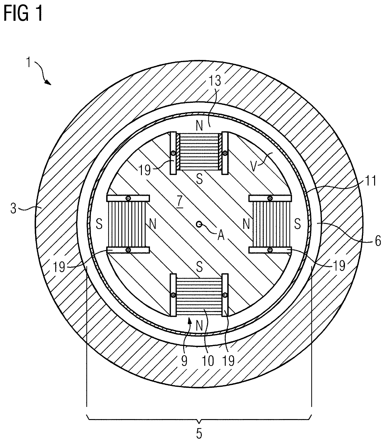
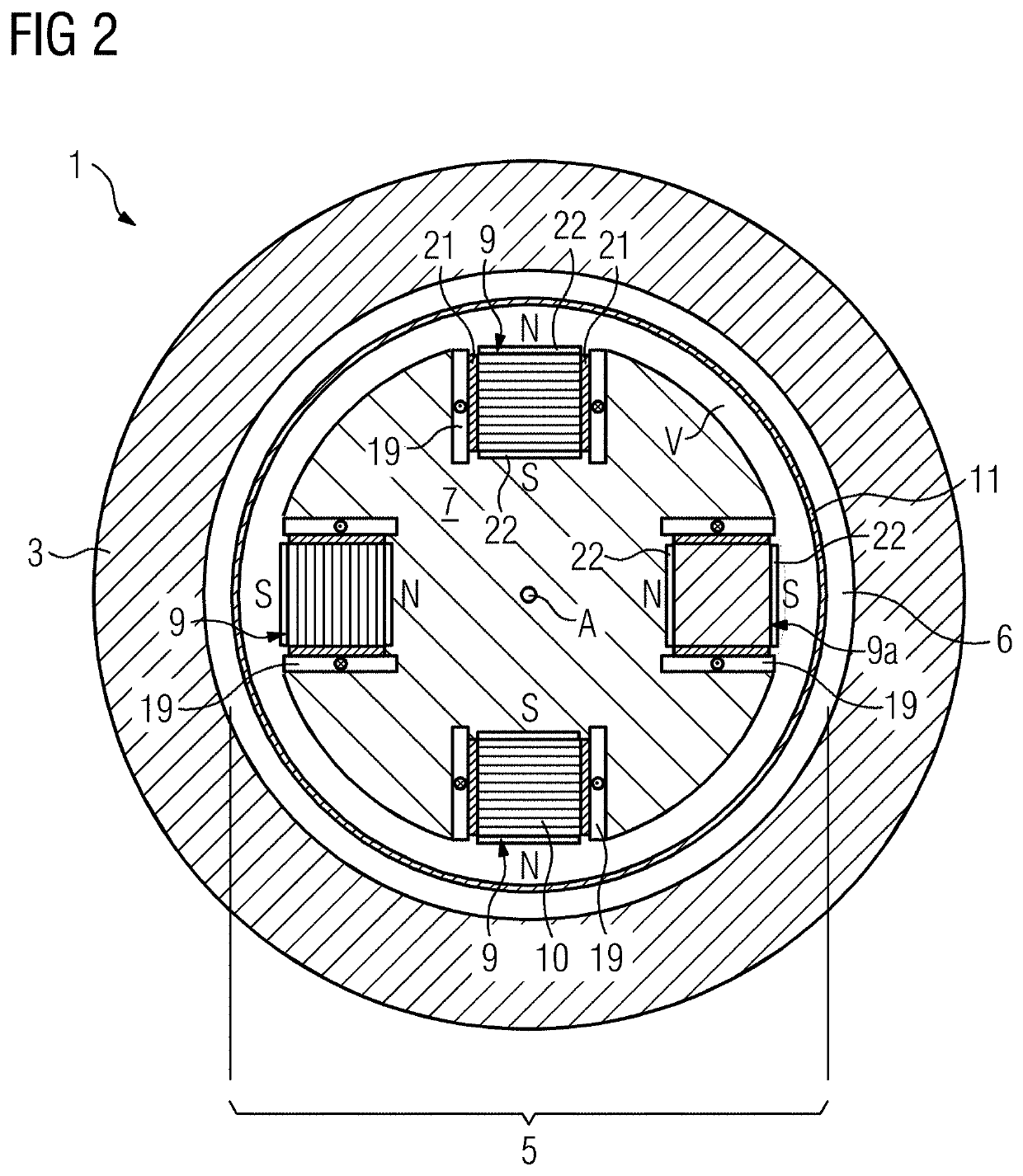
[0054]FIG. 1 shows a schematic cross section of an electrical machine 1, that is to say shows the electrical machine perpendicularly to the central axis A. The machine includes an external stator 3, which is arranged in a fixed manner, and an internal rotor 5 which is rotatably mounted about the central axis A. The electromagnetic interaction between the rotor 5 and the stator 3 takes place across the air gap 6 situated between them. The machine is a permanently excited machine which has a plurality of superconducting permanent magnets 9 in order to form an excitation field in the region of the rotor. In the cross section of FIG. 1, here by way of example four permanent magnets of this type are distributed over the circumference of the rotor. They are arranged in corresponding radially outer recesses of a rotor support 7, wherein the rotor support 7 mechanically supports the permanent magnets 9. However, yet further permanent magnets than the four shown here may also be present in t...


PUM


Abstract

The disclosure relates to a rotor for an electrical machine, having a central rotor axis. The rotor includes a rotor carrier and at least one superconducting permanent magnet carried mechanically by the rotor carrier. The rotor further includes a magnetization device having at least one superconducting coil element which surrounds the superconducting permanent magnet and which is suitable for magnetization of the superconducting permanent magnet. Furthermore, an electrical machine including such a rotor and a method for magnetization of at least one superconducting permanent magnet of such a rotor are disclosed.

Description

[0001]The present patent document is a § 371 nationalization of PCT Application Serial No. PCT / EP2019 / 079391, filed Oct. 28, 2019, designating the United States, which is hereby incorporated by reference, and this patent document also claims the benefit of German Patent Application No. 10 2018 218 473.9, filed Oct. 29, 2018, which is also hereby incorporated by reference.TECHNICAL FIELD[0002]The present disclosure relates to a rotor for an electrical machine with a central rotor axis, including a rotor support and at least one superconducting permanent magnet which is mechanically supported by the rotor support. The disclosure furthermore relates to an electrical machine having such a rotor and to a method for magnetizing at least one superconducting permanent magnet of such a rotor.BACKGROUND[0003]The prior art discloses electrical machines having a stator and a rotor and in which the rotor is configured to generate an electromagnetic excitation field. Such an excitation field may ...

Claims


Application Information

Patent Timeline
IPC IPC(8): H02K55/02
CPCH02K55/02H02K55/04H02K21/042H02K3/20H02K15/03H01F6/008H02K1/02Y02E40/60
Inventor ARNDT, TABEAKUMMETH, PETER
Owner ROLLS ROYCE DEUT LTD & CO KG
Why Eureka
Try Eureka