
High pressure resistant bilaterally rotating permanent proportion electro-magnet
A proportional electromagnet and two-way rotation technology, which is applied in the direction of electromagnets with armatures and electromagnets, can solve the problems of inability to directly drive the power stage spool, small output rotation angle and output torque, and small linear working range, etc., to achieve The effect of simple and reliable structure, small nonlinear error and large linear working range
- Summary
- Abstract
- Description
- Claims
- Application Information
AI Technical Summary
Problems solved by technology
Method used
Image

Examples
Embodiment Construction
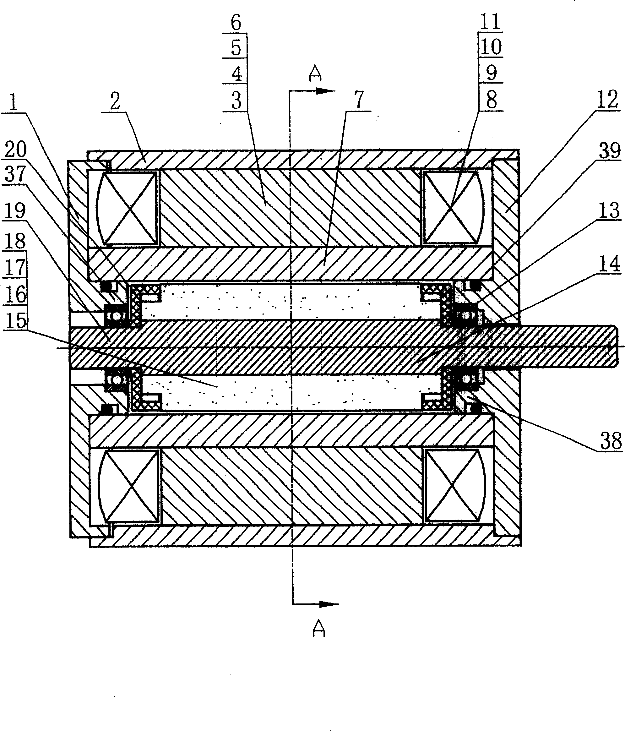
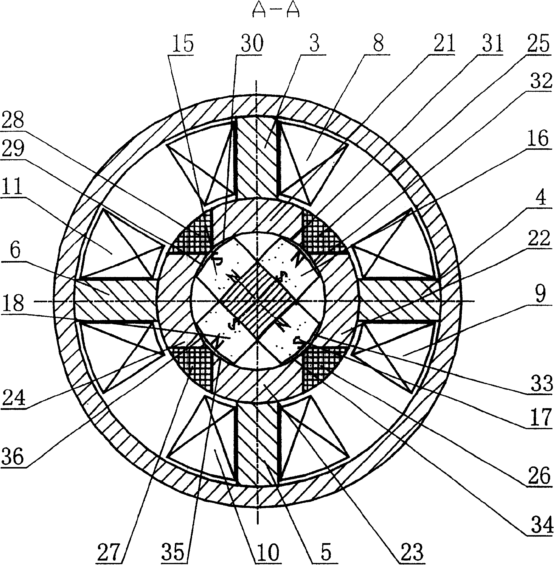
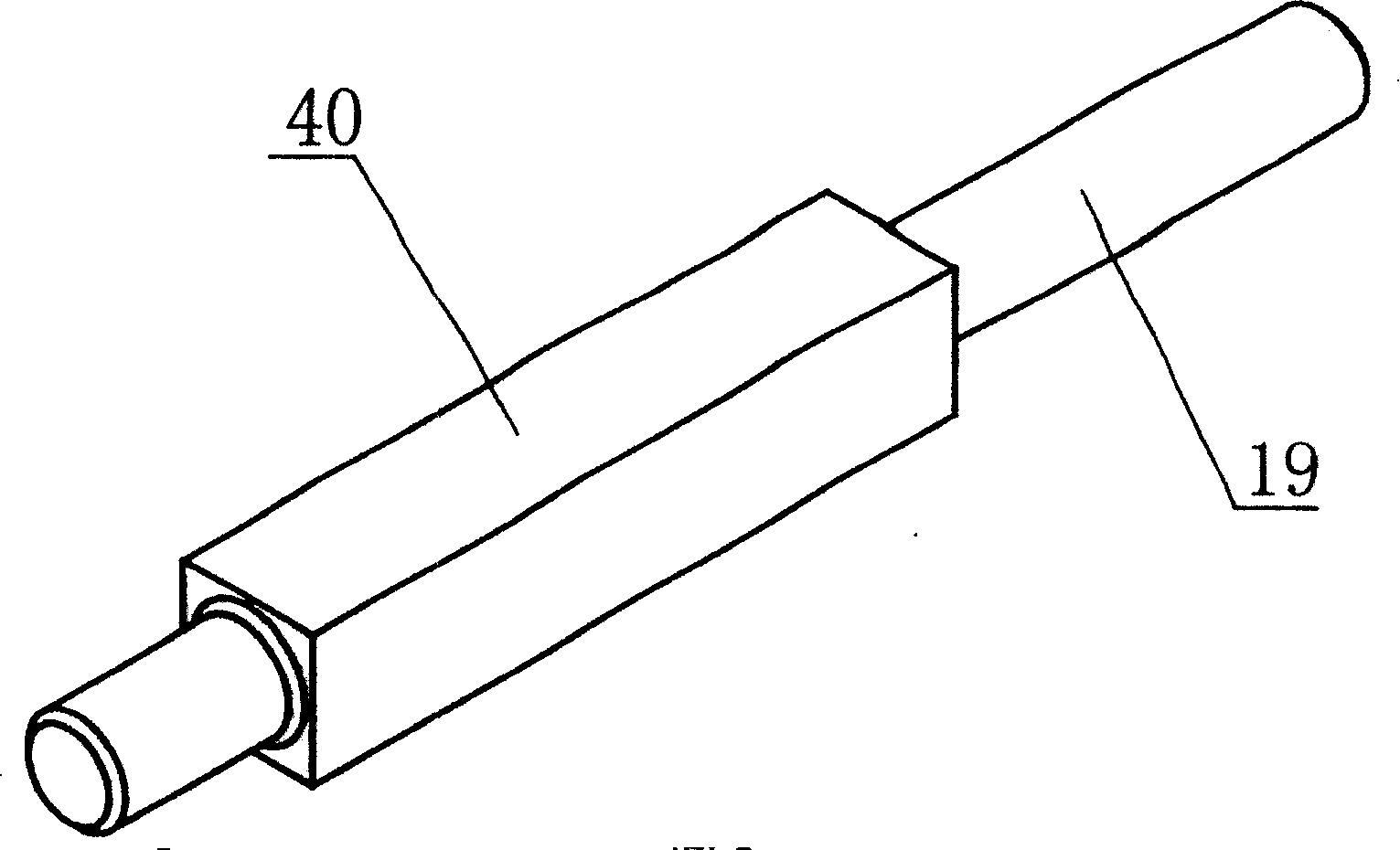
[0025] The present invention takes a quadrupole structure as an example, and the present invention will be further described below in conjunction with the accompanying drawings.
[0026] Figure 1, figure 2 , image 3 As shown, the present invention includes stator pole piece 7, armature rotor 14, yokes 3, 4, 5, 6, housing 2, control coils 8, 9, 10, 11, front end cover 1, rear end cover 12, bearing 13 The stator pole piece 7 is divided into four parts by the non-magnetic conductors 25, 26, 27, 28 evenly along the circumferential direction and welded into four parts, the magnetic conductors 21, 22, 23, 24, which can withstand high fluid pressure inside; The pole shoe 7 is fixed to the rear end cover 12, and the front end cover 1 and the rear end cover 12 are respectively fixed on the housing 2; the stator pole shoe 7 is equipped with an armature rotor 14, and the armature rotor 14 is composed of four permanent magnets arranged radially symmetrically. 15, 16, 17, 18 and rotatin...
PUM
 Abstract
Description
Claims
Application Information