Anti-high voltage permanent magnet polarized two-way ratio electromagnet

A proportional electromagnet, polarized technology, applied in the direction of the electromagnet with armature, electromagnet, valve details, etc., can solve the problems of the static power consumption of the system is not effectively suppressed, the dynamic characteristics are reduced, the size of the electromagnet is large, etc. To achieve the effect of strong anti-interference, reducing heat generation, simple structure and process

Inactive Publication Date: 2006-06-07
ZHEJIANG UNIV +1
View PDF2 Cites 4 Cited by
  • Summary
  • Abstract
  • Description
  • Claims
  • Application Information

AI Technical Summary

Problems solved by technology

However, this combined two-way proportional electromagnet has a large volume, and its dynamic characteristics are greatly reduced due to the increase in weight.
Invention patent 85103757 "High Voltage Bidirectional Polarized Proportional Electromagnet" discloses a high voltage bidirectional polarized proportional electromagnet with bidirectional continuous output force, no zero dead zone, simple structure, and high power-to-weight ratio. The energy consumption is very large, and the improvement of the performance of the proportional electromagnet is limited due to structural and technological reasons; the invention patent 88101723.x "bidirectional proportional electromagnet with amplifier" discloses a high-voltage resistant bidirectional proportional Electromagnet, on the basis of invention patent 85103757, effectively reduces system energy consumption, simplifies circuit structure and design process, but it needs to provide a certain base value of input current first, so that the static power consumption of the system is not effectively suppressed

Method used


Image

  • Anti-high voltage permanent magnet polarized two-way ratio electromagnet
  • Anti-high voltage permanent magnet polarized two-way ratio electromagnet
  • Anti-high voltage permanent magnet polarized two-way ratio electromagnet

Examples


Embodiment Construction

[0021] The present invention will be further described below in conjunction with drawings and embodiments.

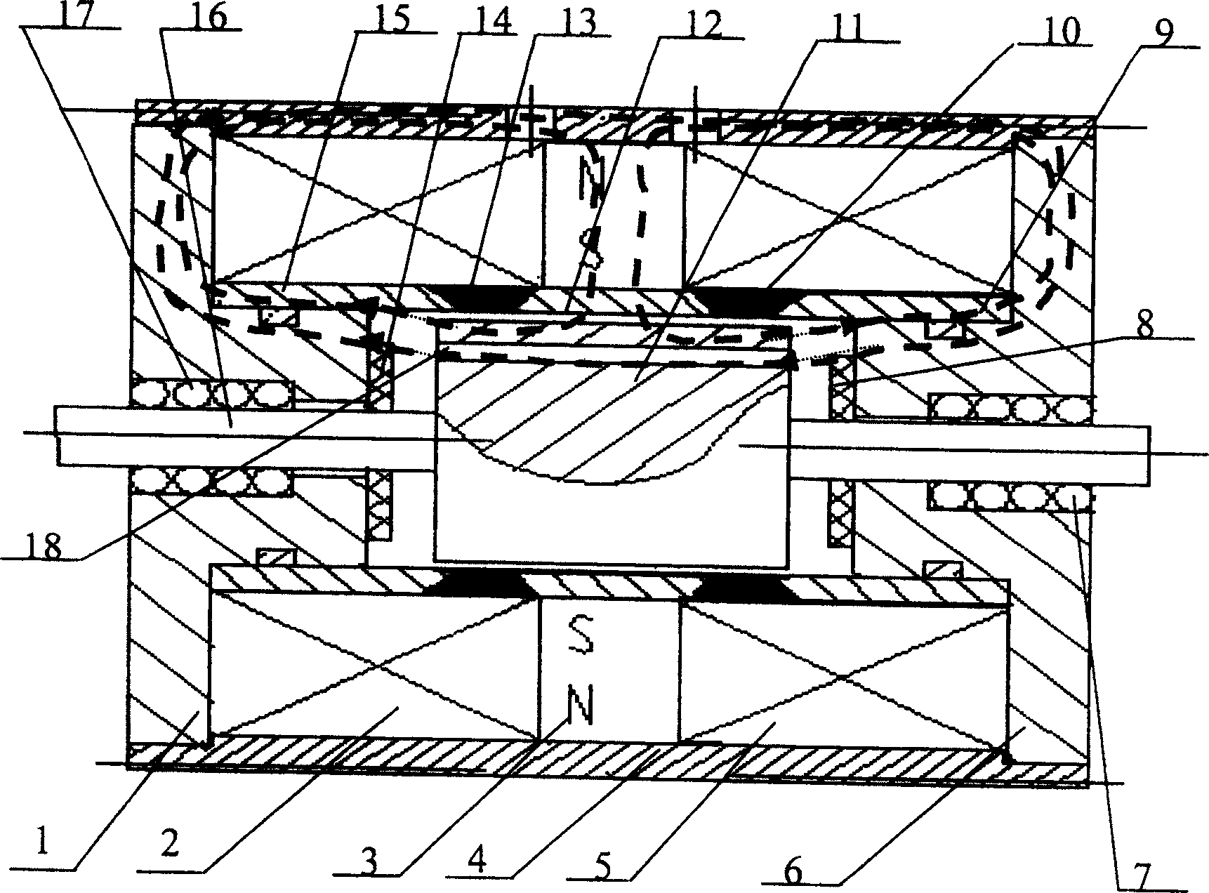
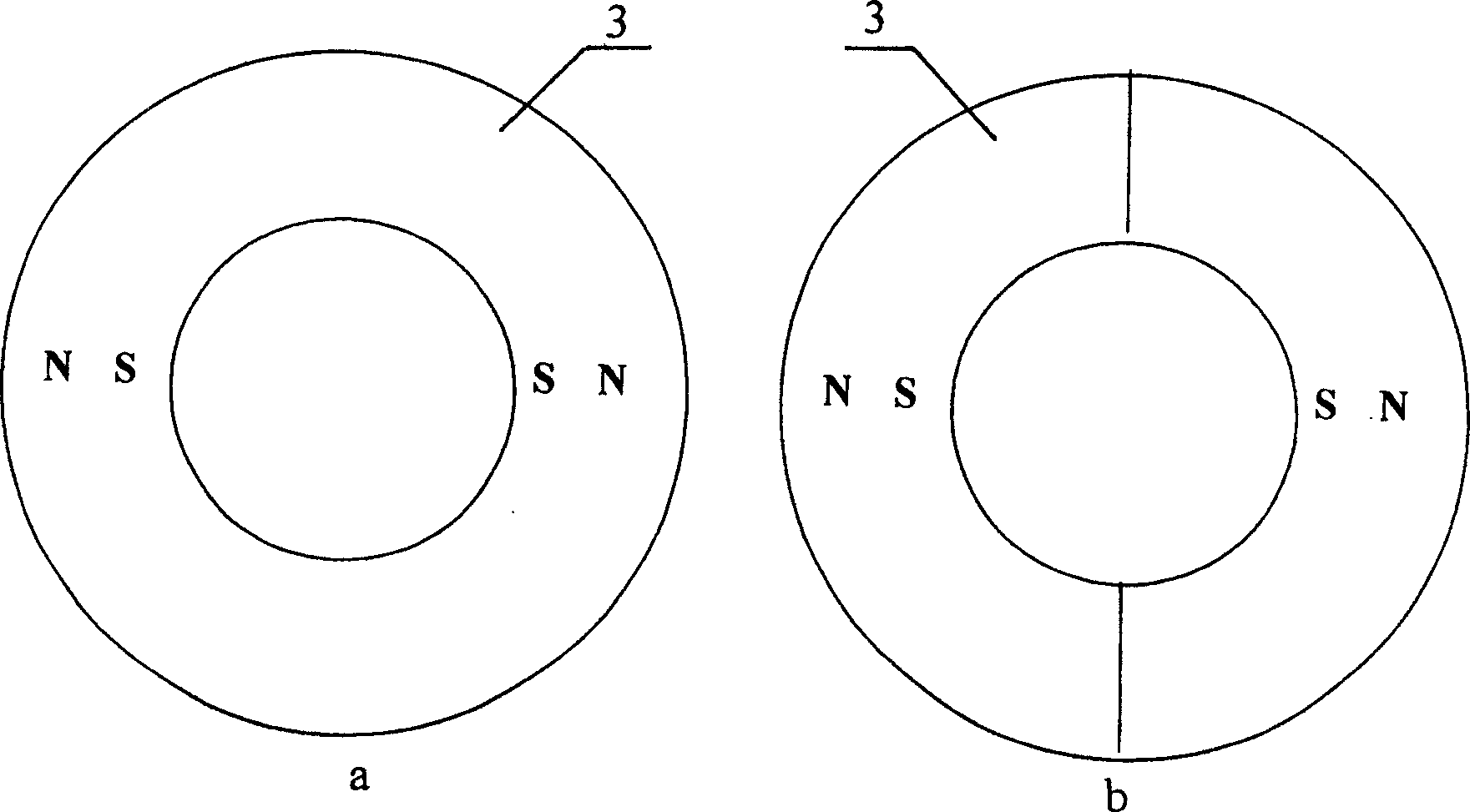
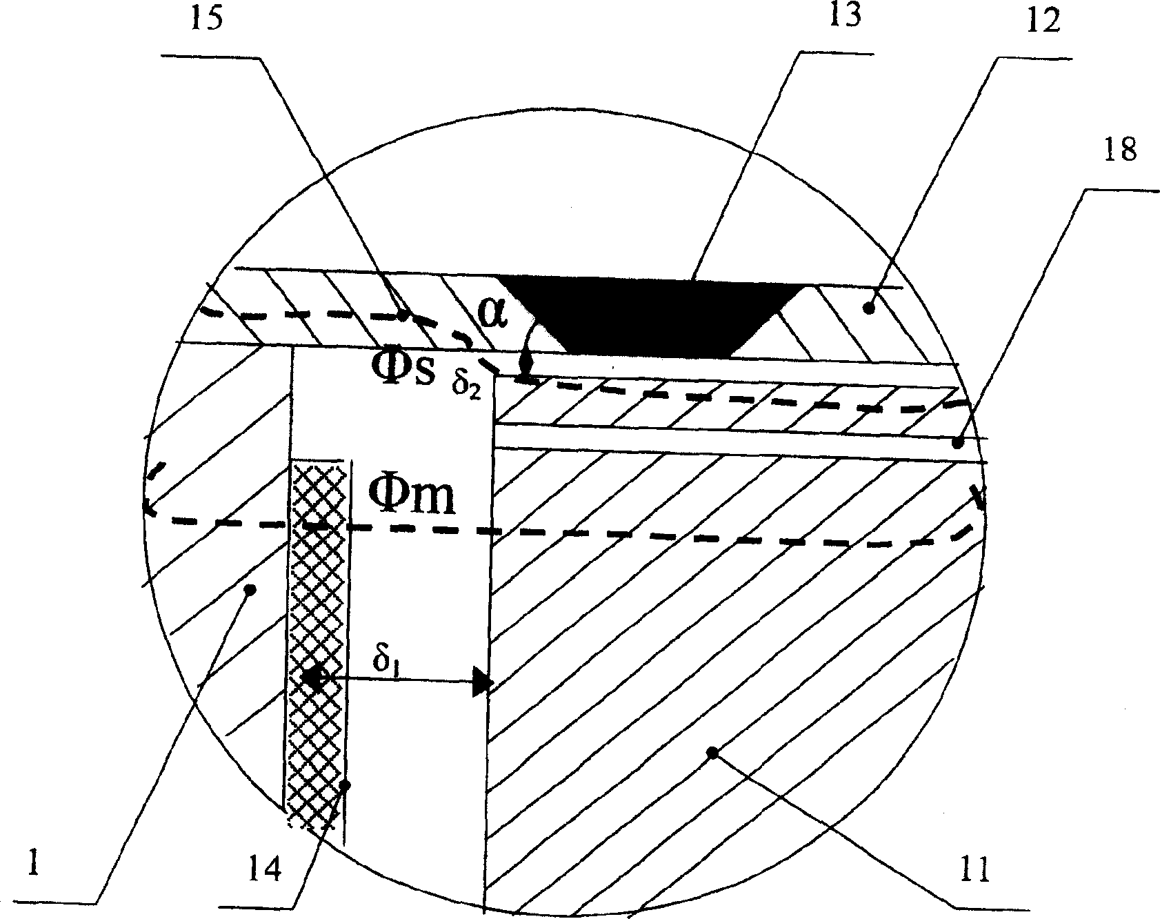
[0022] exist figure 1 Among them, the present invention includes a basin composed of a guide sleeve, yokes 1 and 6 installed in the holes at both ends of the guide sleeve, and an armature 11 with output push rods 16 at both ends of the guide sleeve and the holes of the two yokes 1 and 6. Shaped pole shoe parts; control coils 2, 5 are respectively installed on both sides of the guide sleeve in the housing 4; the guide sleeve is divided into three sections of guide sleeves 9, 12, 15 with non-metallic magnetic isolation rings 10, 13 and welded into one overall. Ring-shaped permanent magnet 3 is housed on the guide sleeve 12 of middle section. The two basin-shaped pole pieces have an included angle α with the respective guide sleeves 15 and 9 respectively.

[0023] The shell 4 is made of a hollow shell with good magnetic permeability. The middle part of the housing 4 ha...


PUM


Abstract

The invention discloses a high-voltage permanent magnet polarized bidirectional proportional electromagnet. It is an electro-mechanical conversion mechanism for proportional valves and servo valves in fluid control systems. The high-voltage permanent magnet polarized bidirectional proportional electromagnet adopts a specially designed bidirectional basin-shaped pole shoe structure composed of yoke iron and guide sleeve. A permanent magnet is installed in the middle of the guide sleeve, and control coils are installed on both sides of the permanent magnet. The permanent magnet generates The polarized magnetic field and the control magnetic field generated by the control coil are differentially superimposed, and a bidirectional and continuous output force proportional to the input signal can be obtained on the armature, and a good proportional control characteristic is obtained. The high-voltage permanent magnet polarized bidirectional proportional electromagnet has low energy consumption, eliminates zero dead zone, and has good static and dynamic characteristics. Therefore, the present invention can be widely applied to proportional valves and servo valves.

Description

Technical field [0001] The invention relates to an electro-mechanical conversion mechanism for a proportional valve and a servo valve in a fluid control system, in particular to a high-voltage-resistant permanent magnet polarized bidirectional proportional electromagnet. Background technique [0002] Traditional proportional electromagnets can only provide one-way driving capability, so in order to obtain two-way driving, two proportional electromagnets are often combined for driving. However, this combined two-way proportional electromagnet has a large volume, and its dynamic characteristics are also greatly reduced due to the increase in weight. Invention patent 85103757 "High Voltage Bidirectional Polarized Proportional Electromagnet" discloses a high voltage bidirectional polarized proportional electromagnet with bidirectional continuous output force, no zero dead zone, simple structure, and high power-to-weight ratio. The energy consumption is very large, and the impro...

Claims


Application Information

Patent Timeline
Patent Type & Authority Patents(China)
IPC IPC(8): H01F7/08F16K31/06
Inventor 丁凡李其朋翁振涛毕晴春
Owner ZHEJIANG UNIV
Why Eureka
Try Eureka