Rotor coreless magnetic pole structure and design method of a two-pole permanent magnet synchronous motor

A technology of permanent magnet synchronous motor and magnetic pole structure, which is applied in the direction of synchronous motor with stationary armature and rotating magnet, magnetic circuit shape/style/structure, magnetic circuit rotating parts, etc. The magnetic direction changes too much and the magnetic density of the yoke is high, so as to achieve the effect of simple magnetization, high sine degree and high-efficiency operation

Active Publication Date: 2021-09-24
DALIAN UNIV OF TECH
View PDF0 Cites 0 Cited by
  • Summary
  • Abstract
  • Description
  • Claims
  • Application Information

AI Technical Summary

Problems solved by technology

[0005] However, for two-pole motors, Halbach permanent magnet arrays with three to five segments per pole are used. The magnetization direction of each segment varies too much, and the generated air gap magnetic field contains a large number of harmonics, and the magnetic density of the yoke is also high. , it is difficult to cancel the rotor core
If the number of segments per pole is increased, the magnetization becomes more complicated
For this reason, it is necessary to invent a rotor coreless magnetic pole structure suitable for two-pole permanent magnet synchronous motors, which can be like the continuously magnetized Halbach permanent magnet array, and the magnetization direction of each segment of the magnet can be continuously changed to produce a sinusoidally distributed air gap Magnetic field; and it will not complicate magnetization due to too many segments per pole

Method used


Image

  • Rotor coreless magnetic pole structure and design method of a two-pole permanent magnet synchronous motor
  • Rotor coreless magnetic pole structure and design method of a two-pole permanent magnet synchronous motor
  • Rotor coreless magnetic pole structure and design method of a two-pole permanent magnet synchronous motor

Examples


Embodiment Construction

[0042] In order to make the content of the present invention more clearly understood, the present invention will be further described in detail below based on specific embodiments and in conjunction with the accompanying drawings.

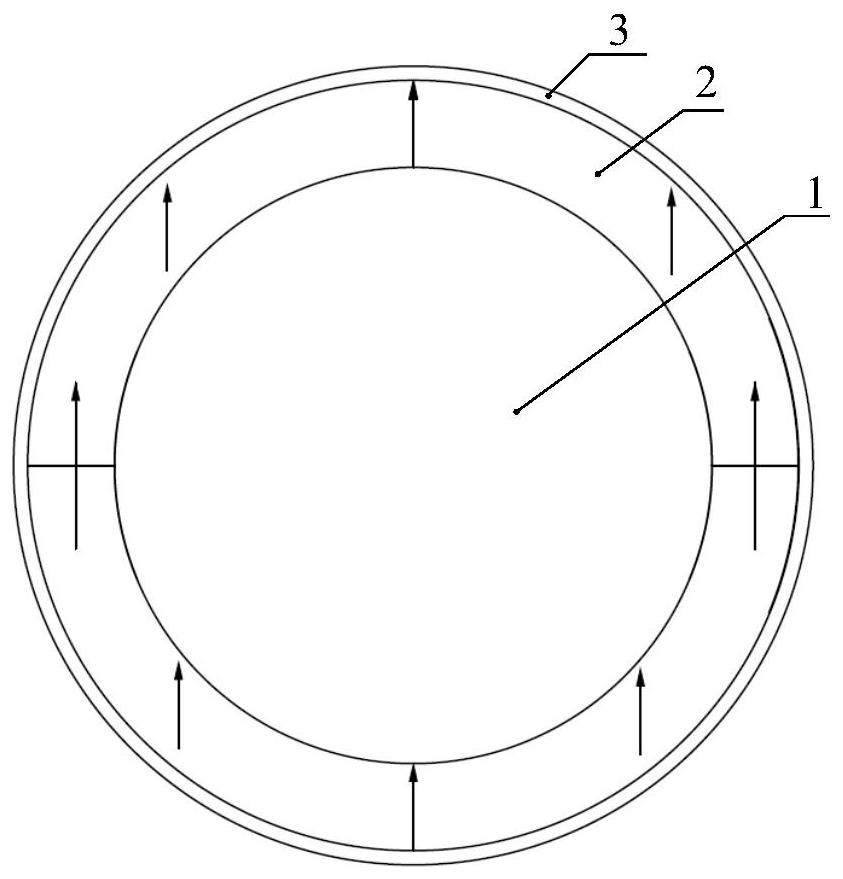
[0043] A 2-pole permanent magnet synchronous motor with a rated power of 75kW and a rated speed of 33000r / min. It is required that the outer diameter of the stator is 150mm, the length of the stator iron is 140mm, and the length of the air gap is 1.75mm. According to the design method of the present invention, it is calculated that the diameter of the titanium alloy rotating shaft is 45mm, the thickness of the permanent magnet is 6.5mm, the thickness of the protective cover is 1mm, and the outer diameter of the rotor is 60mm.

[0044] With the magnetic pole structure of the present invention, the magnetic pole is composed of two magnets, and the magnetization direction of the magnet is parallel to the center of the magnetic pole. When a current of...


PUM

PropertyMeasurementUnit
lengthaaaaaaaaaa

Abstract

The invention discloses a rotor coreless magnetic pole structure and design method of a two-pole permanent magnet synchronous motor, belonging to the field of permanent magnet motors. The structure includes a rotating shaft, a permanent magnet array and a protective sleeve, and the permanent magnet array is pasted on the rotating shaft; the permanent magnet array is composed of N segments of permanent magnets to form a ring-shaped magnetic pole, and N is an even number of one or more than two, and the number of N depends on the diameter of the magnetic pole The power of the magnetizer is determined; the magnetization direction of the N-segment permanent magnets of the permanent magnet array is the same, and they are all parallel to the center of the magnetic pole of the motor, and the protective sleeve and the permanent magnet array have an interference fit. The invention is suitable for two-pole high-speed permanent-magnet synchronous motors, can cancel the rotor iron core, and generates an air-gap magnetic field with high sine degree. The magnetization of the permanent magnet array is simple, and the magnetization direction does not need to be changed; for small-power motors, the entire ring can be magnetized in parallel; for high-power motors, the magnetic poles can be divided into several even segments for magnetization. It effectively solves the torque ripple problem of the permanent magnet synchronous motor, and can ensure the motor to run more smoothly and efficiently in the electric drive system.

Description

technical field [0001] The invention belongs to the field of permanent magnet motors, and relates to a magnetic pole structure and a design method of a high-speed permanent magnet motor without an iron core in the rotor. Background technique [0002] The high-speed motor can directly drive the high-speed load, and the transmission mechanism is eliminated, which not only reduces the volume and weight of the equipment, but also improves the system efficiency and reduces the system noise. At the same time, high-speed motors have a series of advantages such as high efficiency, high power density, small moment of inertia, fast dynamic response, and excellent control performance. They have good applications in high-speed direct drive fields such as aeration fans, centrifugal compressors, aerospace, and new energy. Application prospect. [0003] The speed of high-speed permanent magnet synchronous motors used in aeration fans and fuel cell compressors reaches tens of thousands to ...

Claims


Application Information

Patent Timeline
Patent Type & Authority Patents(China)
IPC IPC(8): H02K21/14H02K1/27H02K1/28H02K1/24
CPCH02K1/24H02K1/278H02K1/28H02K21/14H02K2213/03
Inventor 孙建忠白凤仙
Owner DALIAN UNIV OF TECH
Why Eureka
Try Eureka