
A Halbach Array Coupler

A Halbeck, array-type technology, applied in the field of magnetic induction, can solve the problems of magnetic induction line loss, magnetic drop and disappearance of couplers, etc., and achieve the effects of reducing magnetic flux leakage, reducing magnetic induction line loss, and high torque density

Active Publication Date: 2020-06-26
ANHUI UNIV OF SCI & TECH
View PDF8 Cites 0 Cited by
  • Summary
  • Abstract
  • Description
  • Claims
  • Application Information

AI Technical Summary

Problems solved by technology

The present invention is mainly used to solve the problem that when the existing magnetic coupler is used on a truck in a perennially hot area, the internal parts will be damaged due to the vibration force, and in such a high temperature environment, the magnetism in the coupler will easily decrease or disappear. At the same time, due to the magnetic flux leakage phenomenon of the magnetic coupler, it will cause the loss of the magnetic induction line, which will affect the transmission efficiency of the magnetic coupler.

Method used


Image

  • A Halbach Array Coupler
  • A Halbach Array Coupler
  • A Halbach Array Coupler

Examples


Embodiment Construction

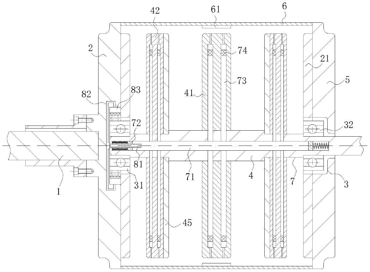
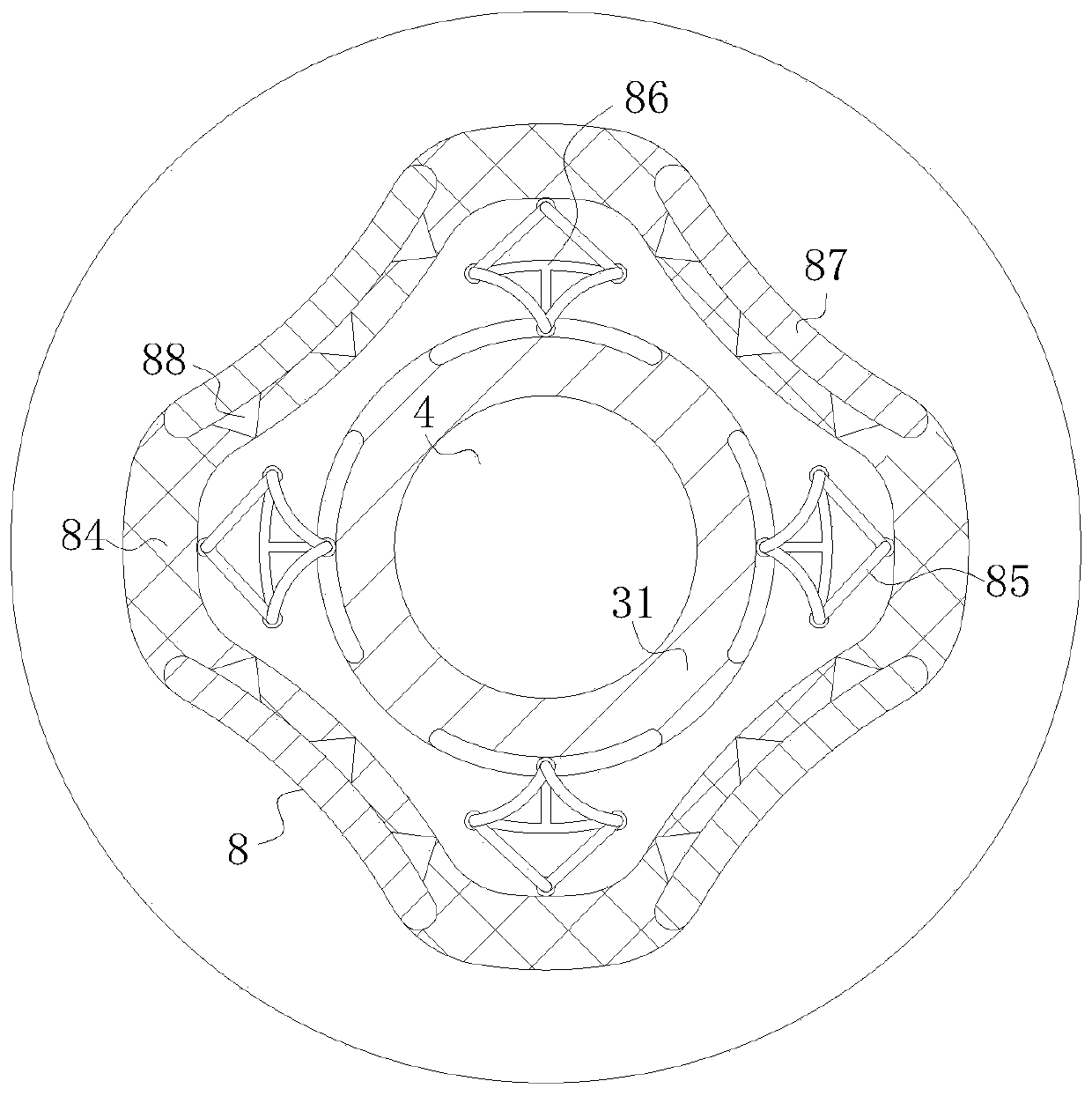
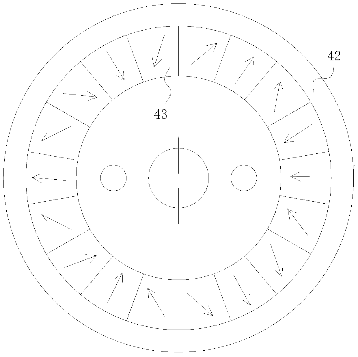
[0020] use Figure 1-Figure 4 A Halbach array coupler according to one embodiment of the present invention will be described below.

[0021] Such as Figure 1-Figure 4 As shown, a Halbach array coupler according to the present invention includes an input shaft 1, an input end cover 2, a bearing set 3, an output shaft 4, an output end cover 5, a casing 6, a cooling mechanism 7 and a buffer mechanism 8 The bearing group 3 includes a No. 1 bearing 31 and a No. 2 bearing 32; the input end cover 2 and the output end cover 5 are connected through the casing 6, and the outer end of the input end cover 2 is fixedly connected with the input shaft 1 by screws , a No. 1 bearing 31 is rotatably installed in the inner side wall of the input end cover 2, and an axial copper conductor 21 is fixedly installed on the inner surface of the input end cover 2; the inside of the No. 1 bearing 31 is fixedly connected with the output shaft 4; the output The right end of the shaft 4 is rotatably con...


PUM


Abstract

The invention belongs to the technical field of magnetic induction, in particular to a Helbeck array coupler which comprises an input shaft, an input end cover, a bearing group, an output shaft, an output end cover, a shell, a cooling mechanism and a buffer mechanism. The bearing group comprises a first bearing and a second bearing. The input end cover and the output end cover are connected through the shell. The input shaft is fixedly connected on the outer end of the input end cover through screws. The first bearing is rotatably installed in the inner side wall of the input end cover. An axial copper conductor is fixedly installed on the inner surface of the input end cover. The coupler is mainly used for solving the problem that the internal parts are damaged due to shock force when theexisting magnetic coupler is used on the truck in a perennial hot area and the magnetism in the coupler is liable to decrease or disappear in the high temperature environment, and the magnetic flux leakage phenomenon occurs in the magnetic coupler and leads to the loss of the magnetic induction line and thus the transmission efficiency of the magnetic coupler is influenced.

Description

technical field [0001] The invention belongs to the technical field of magnetic induction, in particular to a Halbach array coupler. Background technique [0002] In a microwave system, it is often necessary to divide the microwave power of one path into several paths in proportion, which is the problem of power allocation. The components that realize this function are called power distribution components or couplers, which mainly include: directional couplers, power dividers and various microwave branch devices. [0003] The Halbach Array is a magnet structure, which is an approximate ideal structure in engineering, and the goal is to generate the strongest magnetic field with the least amount of magnets. In 1979, American scholar Klaus Halbach discovered this special permanent magnet structure when he was doing electron acceleration experiments, and gradually perfected this structure, and finally formed the so-called "Halbach" magnet. With the gradual development of the m...

Claims


Application Information

Patent Timeline
Patent Type & Authority Patents(China)
IPC IPC(8): H02K49/10H02K9/19H02K1/32
CPCH02K1/32H02K9/19H02K49/106H02K49/108H02K2213/03
Inventor 王爽李德永郭永存胡坤周军鹏苏畅
Owner ANHUI UNIV OF SCI & TECH
Learn More