Seal

a sealing lip and sealing technology, applied in the direction of engine seals, mechanical devices, engine components, etc., can solve the problem of needing to fasten magnetizable layers, and achieve the effect of increasing the pressure effect of the sealing lip against the mating ring

Active Publication Date: 2014-05-20
CARL FREUDENBERG KG
View PDF8 Cites 0 Cited by
  • Summary
  • Abstract
  • Description
  • Claims
  • Application Information

AI Technical Summary

Benefits of technology

[0003]The invention is based on the object of providing a seal of the type mentioned at the beginning which can easily be produced and has a small number of parts.
[0005]To achieve the object, the sealing lip contains magnetizable particles. The magnetizable particles are firmly embedded in the material of the sealing lip and therefore cannot detach themselves from the sealing lip when they become worn. Production is particularly easy, since the particles can be added to the polymer, the shaping of the sealing lip taking place in a subsequent injection-moulding process. The magnetization of the particles may in this case take place before or after the injection-moulding. The subsequent magnetization can take place easily and inexpensively by means of a magnetizing tool that is known from encoder production. No further production steps are required for producing the sealing lip. In particular, there is no longer any need for measures for fastening magnetizable layers, which are particularly laborious in the case of some plastics often used in sealing technology. The particles are protected from external influences, for example aggressive media, by the embedding in the material of the sealing lip.
[0007]The proportion of magnetizable particles in the sealing lip may be up to 50%. With higher proportions, the influence of the particles on the sealing effect, in particular the sliding properties of the sealing lip, increase greatly and with lower proportions there is an increase in the risk of leakage caused by weaker pressing on account of weaker magnetic forces.
[0009]The sealing lip may form a sealing sleeve, which is made to protrude. Protruded sealing sleeves, in particular made of PTFE, are easy to fit. The pressing by magnetic interaction is in this case particularly advantageous, since the pressing force produced by restoring forces of the sealing lip material is low in the case of protruded sealing lips.
[0012]The seal may be formed as a unitized seal, the unitized seal having a mating ring against which the sealing lip bears with a sealing effect. Unitized seals are often used in machines that are exposed to particularly great contamination. The sealing lip is in this case arranged between the supporting ring and the mating ring and, as a result, is encapsulated and protected against contamination, in particular by coarse particles. The sealing lip thereby bears against the mating ring, whereby the pressing force is produced by magnetic interaction between the sealing lip and the mating ring. This is particularly advantageous in the case of use on shafts with poor magnetic properties, for example shafts made of certain high-grade steel alloys, since the pressing force produced by magnetic interaction would be insufficient in the case of these shafts.
[0013]The portion of the sealing lip that is in contact with the mating ring may have a different polarity than the portion of the mating ring that is in contact with the sealing lip. As a result, the pressing effect of the sealing lip against the mating ring is increased. In the same way as the sealing lip, the mating ring, produced from a metallic material, can be magnetized by simple means.

Problems solved by technology

In particular, there is no longer any need for measures for fastening magnetizable layers, which are particularly laborious in the case of some plastics often used in sealing technology.

Method used


Image

  • Seal
  • Seal
  • Seal

Examples


Embodiment Construction

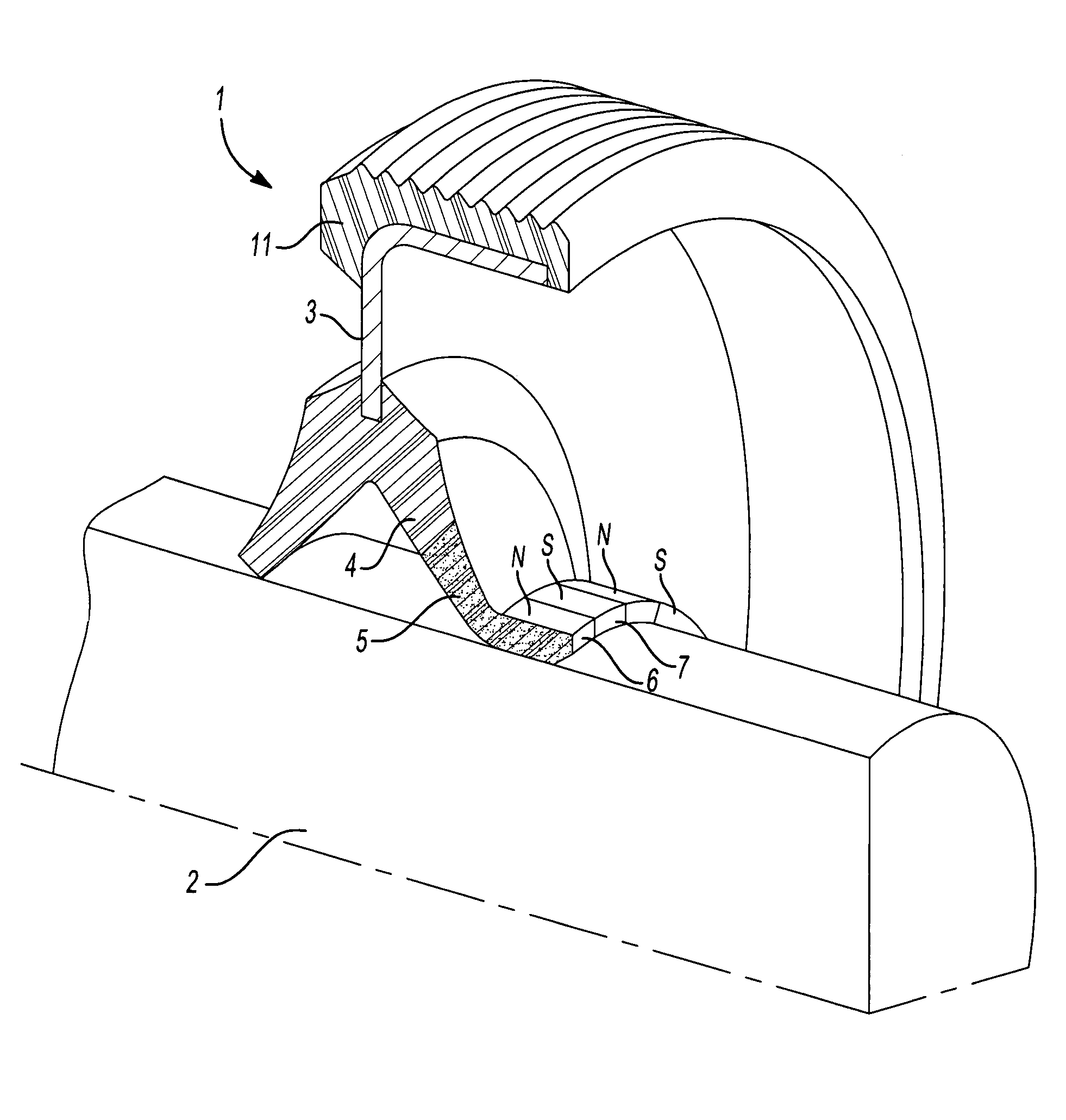
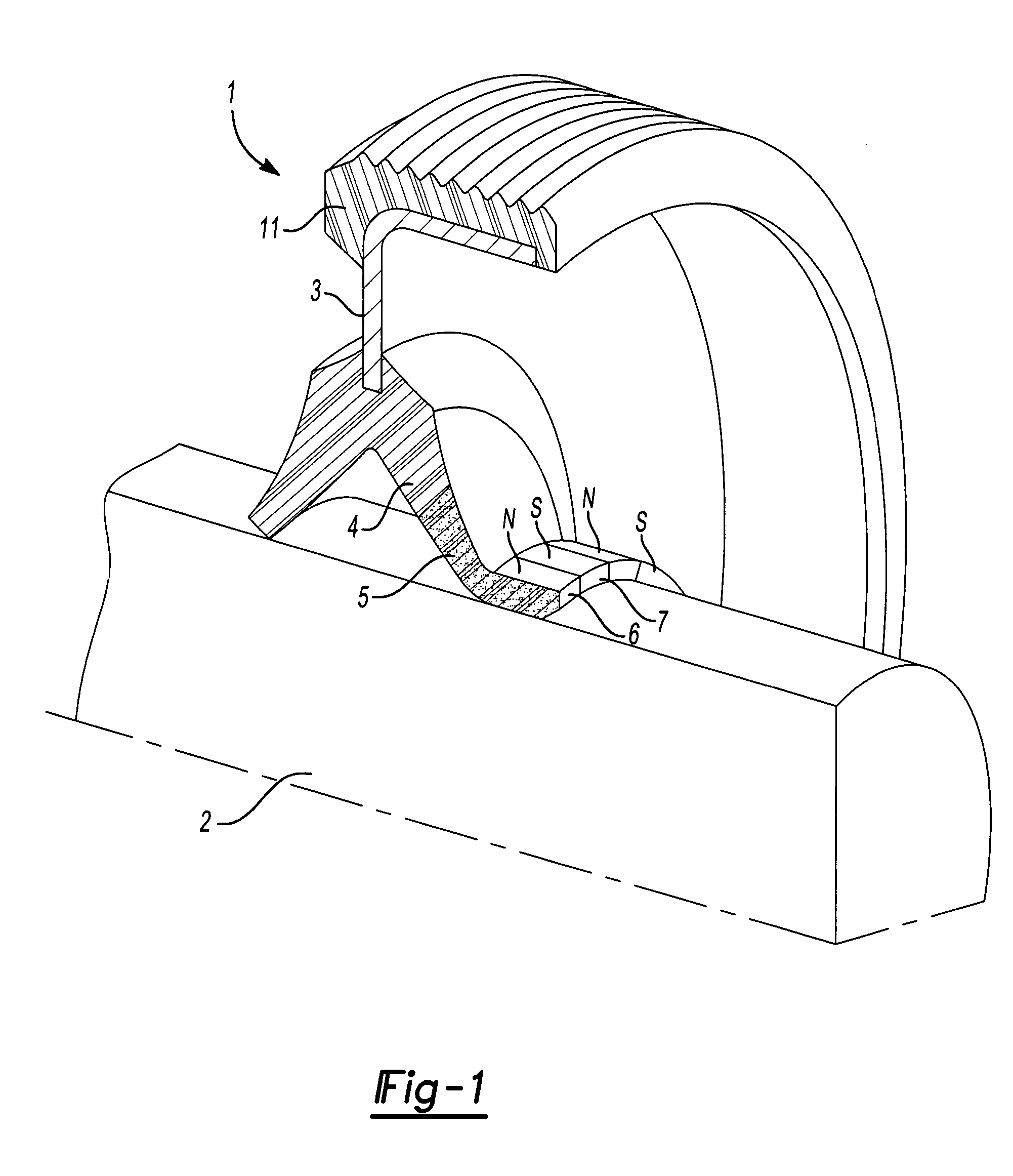
[0018]FIG. 1 shows a seal 1, which is formed as a radial shaft sealing ring and serves for sealing a shaft 2. The seal 1 has a supporting ring 3, which comprises a punched metal part. Fastened to the supporting ring 3 is a sealing lip 4 for dynamically sealing the shaft 2 and a static seal 11 for sealing the housing bore. The sealing lip 4 is made to protrude in a flared manner, the protruded form having been imparted to the sealing lip 4 already before it is put to the intended use. The static seal 11 and the dynamically sealing sealing lip 4 are formed from a polymeric material. The sealing lip 4 is in this case formed from rubber and may partially be given by rubber elongation and comprises ferromagnetic particles 5 in a proportion of 30% to 50%. The average diameter of the particles 5 is 30 nm. The sealing lip 4 with the particles 5 was magnetized on a magnetizing tool, so that pressing of the sealing lip 4 against the shaft 2 takes place by magnetic interaction. In this configu...


PUM


Abstract

Seal (1) for sealing a shaft (2), comprising a supporting ring (3) and at least one sealing lip (4) made of polymeric material, the pressing of the sealing lip (4) against the shaft (2) taking place by magnetic interaction, the sealing lip (4) containing magnetizable particles (5).

Description

TECHNICAL FIELD[0001]The invention relates to a seal for sealing a shaft, comprising a supporting ring and at least one sealing lip made of polymeric material, the pressing of the sealing lip against the shaft taking place by magnetic interaction.PRIOR ART[0002]Seals of this type are known from DE 26 21 352. The previously known seal has a supporting ring with a sealing lip fastened to it. The sealing lip has on the side facing away from the shaft a permanently magnetic layer, which is magnetized in such a way that one side face has one pole and the other side face has the other pole. The supporting ring has a further permanent magnet. The two permanent magnets cause intensified magnetic pressing of the sealing lip against the shaft to be sealed. The magnetically effected pressing permits reliable sealing even under dynamic stress. Leakages of the seal caused by relaxation of the sealing lip are prevented. Furthermore, there is no need for any spring elements, for example annular he...

Claims


Application Information

Patent Timeline
Patent Type & Authority Patents(United States)
IPC IPC(8): F16J15/02
CPCF16J15/3204F16J15/3284
Inventor LUTAUD, DOMINIQUEFOUGEROLLE, FABRICE
Owner CARL FREUDENBERG KG
Why Eureka
Try Eureka