Seal ring and sealed structure

a sealing ring and annular seal technology, applied in the direction of engine seals, mechanical devices, engine components, etc., can solve the problems of lubricating oil leakage to an outside space, increase in torque, and increase in torque, so as to facilitate air vaporization, reduce the shear resistance of the liquid film, and facilitate the discharge of liquid

Pending Publication Date: 2022-05-05
NOK CORP
View PDF3 Cites 1 Cited by
  • Summary
  • Abstract
  • Description
  • Claims
  • Application Information

AI Technical Summary

Benefits of technology

[0007]According to the prior art described above, it is expected that introduction of lubricating oil into the grooves of the seal ring will facilitate formation of an oil film between the seal ring and another member to reduce friction between the seal ring and the another member and thereby reduce a torque. However, if the oil film is of excessive thickness, there is a concern that a shear resistance of the oil film will increase and cause an adverse increase in the torque. Furthermore, if an excessive amount of lubricating oil is introduced into the grooves of the seal ring, there is a concern that some of the lubricating oil may leak to an outside space.
[0009]The present invention provides a seal ring that significantly reduces torque and also reduces an amount of liquid leakage, even when a relative rotational velocity difference of members is large.
[0012]In the present invention, multiple grooves extend in the direction opposite to the main rotational direction of the inner member relative to the seal ring from the open end portions, but do not extend in the main rotational direction from the open end portions. Thus, upon rotation of the inner member relative to the seal ring in the main rotational direction, the grooves facilitate discharge of the liquid from the grooves to thin the film of liquid, thereby reducing a shear resistance of the film of liquid, and facilitate vaporization of air in the liquid by cavitation and form a film of air in each of the grooves. Since the air film has a much lower shear resistance than that of the liquid film, the friction between the seal ring and the another member is significantly reduced, resulting in a reduction in the torque. This effect is particularly remarkable when there is a large difference in the relative rotational velocity of the members. In addition, since the grooves facilitate discharge of the liquid from the groove upon rotation of the inner member relative to the seal ring in the main rotational direction, an amount of leakage of the liquid can be reduced as compared with a case in which the liquid is fed into the grooves.

Problems solved by technology

However, if the oil film is of excessive thickness, there is a concern that a shear resistance of the oil film will increase and cause an adverse increase in the torque.
Furthermore, if an excessive amount of lubricating oil is introduced into the grooves of the seal ring, there is a concern that some of the lubricating oil may leak to an outside space.
Use of conventional seal rings in EVs or xHEVs, gives rise to concerns about increase in torque and about leakage of lubricating oil.

Method used


Image

  • Seal ring and sealed structure
  • Seal ring and sealed structure
  • Seal ring and sealed structure

Examples


Embodiment Construction

[0028]Hereinafter, with reference to the accompanying drawings, various embodiments according to the present invention will be described. It is of note that the drawings are not necessarily to scale, and certain features may be exaggerated or omitted.

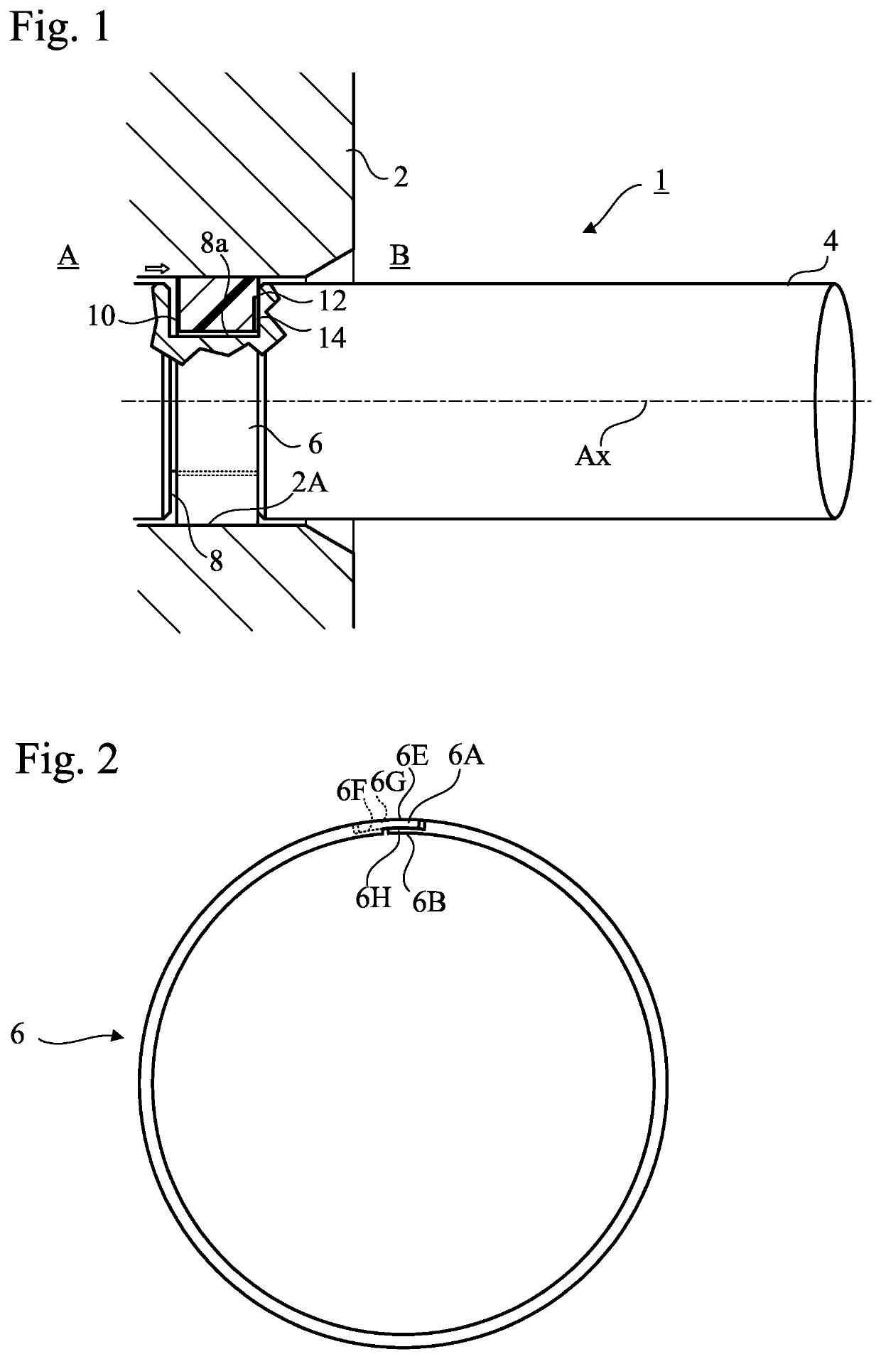
[0029]The sealed structures including seal rings according to embodiments of the present invention described below are used to seal annular gaps between power transmission shafts (motor output shafts) and housings in electric vehicles or hybrid electric vehicles. However, the following description is only illustrative, and the sealed structure with the seal ring according to the present invention can be used to seal liquids, such as a lubricating oil and a coolant, in various oil hydraulic machines, water hydraulic machines, and pneumatic machines. Such machines include, for example, engines, motors, generators, pumps, compressors, power steering devices in automotive vehicles, speed reducers in automotive vehicles, gearboxes in automot...


PUM


Abstract

A circular annular seal ring made of a resin is disposed between an inner member and an outer member that rotate relative to each other. The outer member includes a liquid-storing space and an inner surface having a circular cross section. The inner member is disposed in the liquid-storing space and includes a circumferential groove. The seal ring is stationary relative to the outer member and is slidably disposed in the circumferential groove of the inner member. Grooves are formed on an end surface on an external space side of the seal ring. Each groove has an end portion that opens at an inner peripheral surface of the seal ring, and extends in a direction opposite to a main rotational direction of the inner member relative to the seal ring from the open end portion, but does not extend in the main rotational direction from the open end portion.

Description

TECHNICAL FIELD[0001]The present invention relates to circular annular seal rings and sealed structures having the circular annular seal rings.BACKGROUND ART[0002]Annular seal rings are used to seal annular gaps in various machines that have rotating members. For example, a seal ring is disposed between a power transmission shaft and a housing in an automotive vehicle to seal lubricating oil inside the housing.[0003]Since the seal ring is interposed between members that rotate relative to each other, the seal ring contributes to an increase in rotational torque of the rotating members. To reduce this torque, a technique has been proposed whereby multiple grooves are formed on an end surface of the seal ring to introduce lubricating oil into the grooves upon rotation of the rotating member, as is disclosed in Patent Documents 1 to 3.BACKGROUND DOCUMENTSPatent Document[0004]Patent Document 1: WO 2011 / 105513[0005]Patent Document 2: WO 2011 / 162283[0006]Patent Document 3: Japanese Utilit...

Claims


Application Information

Patent Timeline
Patent Type & Authority Applications(United States)
IPC IPC(8): F16J15/18F16J15/3244
CPCF16J15/182F16J15/3244F16J15/3412
Inventor TADANO, HIKARISEKI, MASATOSHI
Owner NOK CORP
Why Eureka
Try Eureka