Directional LED array with optical foil structure to redirect light

a technology of led arrays and foil structures, applied in the field of light distribution systems, can solve the problems of complex production of directional led arrays and difficulty in controlling other lighting properties with conventional solutions

Active Publication Date: 2022-05-05
SIGNIFY HLDG BV
View PDF2 Cites 0 Cited by
  • Summary
  • Abstract
  • Description
  • Claims
  • Application Information

AI Technical Summary

Benefits of technology

[0062]As indicated above, one or more of the k arrays are comprised by a foil, wherein the foil comprises the respective nk optical elements (and optionally the one or more openings). A single foil can comprise a single 1D array of optical elements. In other embodiments, a single foil may comprise two or more arrays of optical elements. Especially, the foil comprises a polymeric foil. This may e.g. provide flexibility to the lighting device and / or may allow a relative thin lighting device or lighting system. A single foil is especially an embodiment of a single element.
[0063]Alternatively or additionally, the lighting system comprises a second foil comprising the first beam shaping elements. A single foil may comprise a single 1D array of first beam shaping elements. In other embodiments, a single element may comprise two or more arrays of first beam shaping elements. Even more especially, a single foil may comprise all first beam shaping elements. Especially, such second foil may comprise a polymeric foil. This may e.g. provide flexibility to the lighting device and / or may allow a relative thin lighting device or lighting system.

Problems solved by technology

Producing a directional LED array is complex if individual LED nodes and / or optical elements have different orientations.
Likewise, it may be difficult to control other lighting properties with conventional solutions.

Method used


Image

  • Directional LED array with optical foil structure to redirect light
  • Directional LED array with optical foil structure to redirect light
  • Directional LED array with optical foil structure to redirect light

Examples


Embodiment Construction

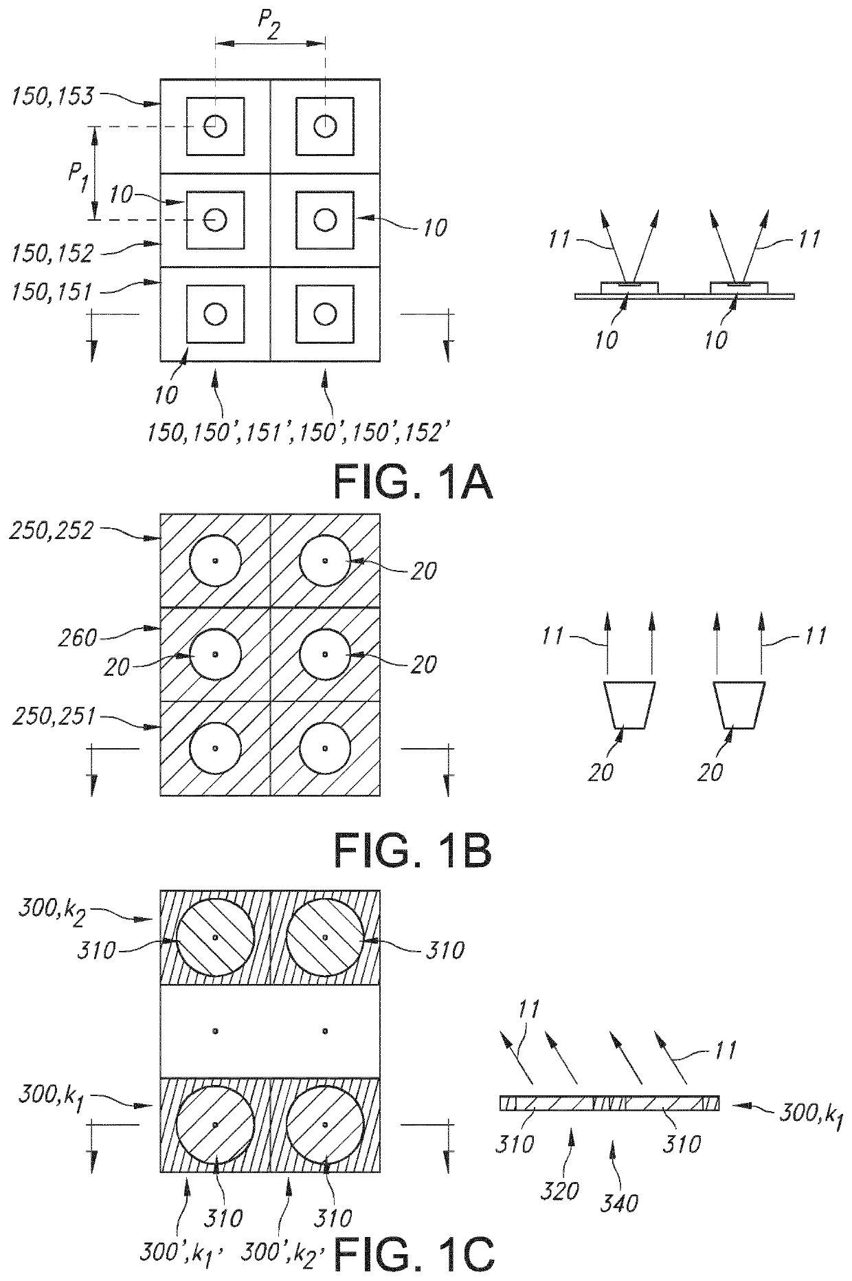
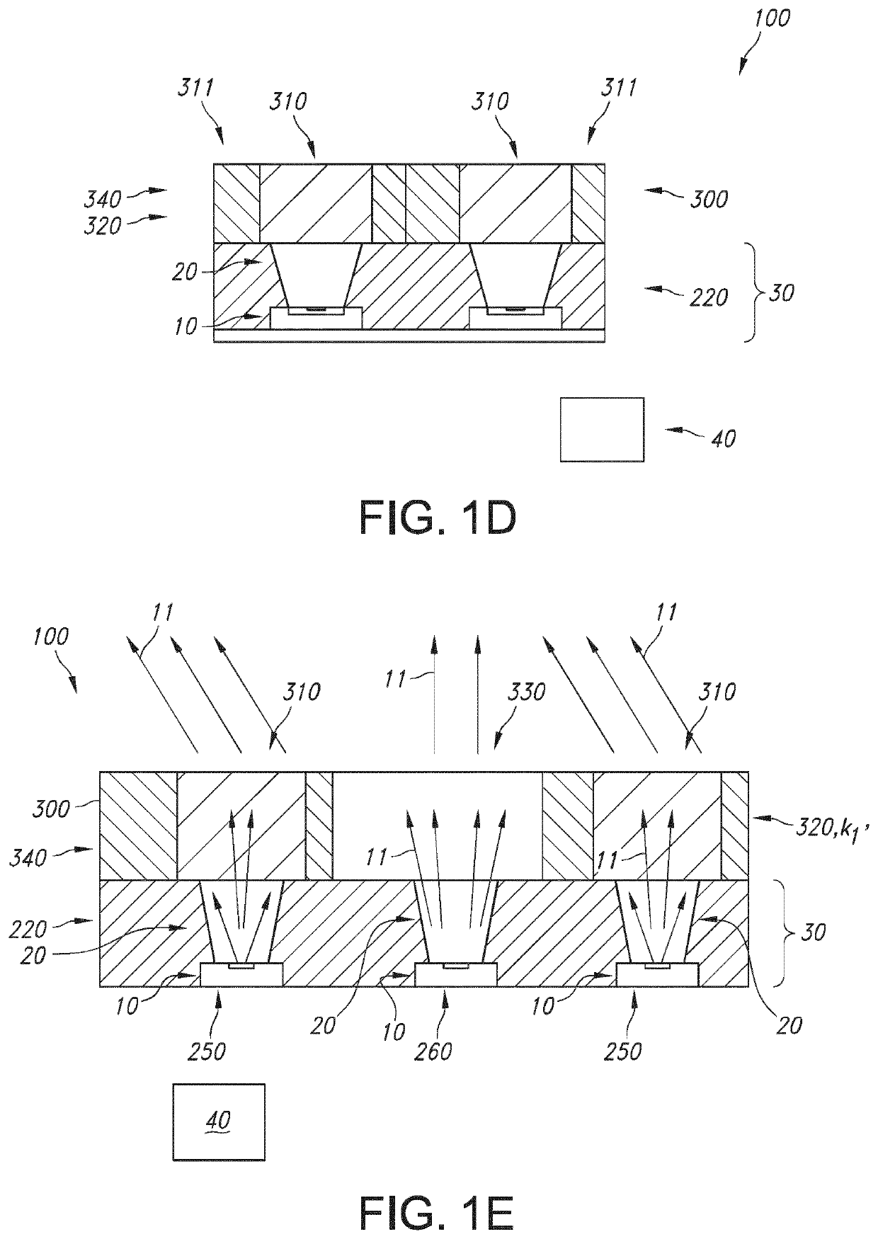
[0081]FIGS. 1a-1c schematically depict cross-section in a plane of the light sources (1a), first beam shaping elements (1b), and optical elements (1c) of a schematic embodiment of a lighting system 100, which is schematically depicted in FIGS. 1d and 1e.

[0082]FIG. 1a schematically depicts a plurality of n light sources 10. From one row of light sources 10, another cross-section is schematically depicted. Each of the n light sources 10 is configured to generate light source light 11. Here, n is by way of example 6.

[0083]In FIG. 1a different subset 150 of light sources 10 may be defined. A non-limiting number of examples is given:[0084]there may be three subsets 150, indicated with first subset 151, second subset 152, and third subset 153, respectively, with, in this embodiment each two light sources 10. Hence, in this embodiment there are three arrays of each two light sources; or[0085]there may be two subsets 150, indicated for the sake of distinction with reference 150′, wherein t...


PUM

PropertyMeasurementUnit
wavelengthaaaaaaaaaa
correlated color temperatureaaaaaaaaaa

Abstract

The invention provides a lighting system (100) comprising: —a plurality of n light sources (10), wherein each of the n light sources (10) is configured to generate light source light (11); —a plurality of n first beam shaping elements (20), wherein each of the n first beam shaping elements (20) is configured downstream of a respective light source (10); —k arrays (300) of optical elements (310), wherein each of the k arrays (300) comprises nk optical elements (310), wherein each of the nk optical elements (310) is configured downstream of a respective first beam shaping element (20) from a subset (250) of the n first beam shaping elements (20); wherein the optical elements (310) are configured to influence one or more of (i) a beam direction of the light source light (11), (ii) a beam shape of the light source light (11), (iii) a spectral distribution of the light source light (11), and (iv) an intensity of the light source light (11); and wherein n≥2, k≥1, and 1≤nk≤n.

Description

FIELD OF THE INVENTION[0001]The invention relates to a lighting system as well as to a kit of parts, e.g. to assemble such lighting system. The invention also relates to a method for providing such lighting system. Yet further, the invention relates to a specific use of the lighting system.BACKGROUND OF THE INVENTION[0002]Beam shaping is essential in all lighting applications. One category of beam shaping optical elements includes classical elements such as reflectors and collimators as used in most luminaires. Traditionally, elements belonging to this category are bulky whereas those in the second category are difficult to design and expensive to manufacture. Solutions for influencing a beam of light are known in the art. US2016 / 0298822, for instance, describes a lighting unit comprising an arrangement of a plurality of light source units configured to emit light, a first foil comprising a plurality of transmissive first foil regions, wherein each first foil region comprises a plur...

Claims


Application Information

Patent Timeline
Patent Type & Authority Applications(United States)
IPC IPC(8): G02B19/00F21V5/00F21V7/00
CPCG02B19/0061F21Y2105/10F21V7/0083F21V5/007G02B19/0019F21V5/008F21V13/04F21Y2115/10
Inventor BERGMAN, ANTHONIE HENDRIKVAN DE SLUIS, BARTEL MARINUS
Owner SIGNIFY HLDG BV
Why Eureka
Try Eureka