System and method for additively printing extension segments on workpieces

Pending Publication Date: 2022-05-12
GENERAL ELECTRIC CO
View PDF2 Cites 0 Cited by
  • Summary
  • Abstract
  • Description
  • Claims
  • Application Information

AI Technical Summary

Benefits of technology

The invention has various benefits that will be explained in detail below.

Problems solved by technology

As such, the tips of the blades incur wear from rubbing against shrouds, chemical degradation or oxidation from hot gases, fatigue from cyclic loading and unloading, diffusion creep of crystalline lattices, and so forth.
Worn blades may, in turn, degrade the performance of the gas turbine engine.

Method used


Image

  • System and method for additively printing extension segments on workpieces
  • System and method for additively printing extension segments on workpieces
  • System and method for additively printing extension segments on workpieces

Examples


Embodiment Construction

[0016]Reference now will be made in detail to exemplary embodiments of the presently disclosed subject matter, one or more examples of which are illustrated in the drawings. Each example is provided by way of explanation and should not be interpreted as limiting the present disclosure. In fact, it will be apparent to those skilled in the art that various modifications and variations can be made in the present disclosure without departing from the scope or spirit of the present disclosure. For instance, features illustrated or described as part of one embodiment can be used with another embodiment to yield a still further embodiment. Thus, it is intended that the present disclosure covers such modifications and variations as come within the scope of the appended claims and their equivalents.

[0017]It is understood that terms such as “top”, “bottom”, “outward”, “inward”, and the like are words of convenience and are not to be construed as limiting terms. As used herein, the terms “firs...


PUM

PropertyMeasurementUnit
Speedaaaaaaaaaa
Strengthaaaaaaaaaa
Energyaaaaaaaaaa

Abstract

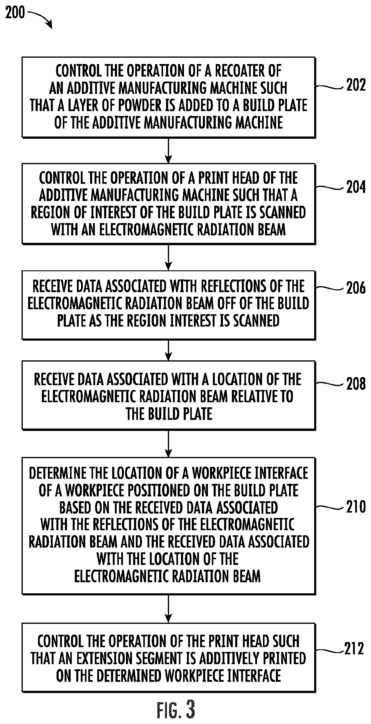
A method for additively printing extension segments on workpieces using an additive manufacturing machine includes controlling, with a computing system, an operation of a print head of the machine such that a region of interest of a build plate of the machine is scanned with an electromagnetic radiation beam. Additionally, the method includes receiving, with the computing system, data associated with reflections of the beam off of the build plate as the region interest is scanned. Furthermore, the method includes receiving, with the computing system, data associated with a location of the beam relative to the build plate. Moreover, the method includes determining, with the computing system, a location of a workpiece interface based on the received data. In addition, the method includes controlling, with the computing system, the operation of the print head such that an extension segment is additively printed on the determined workpiece interface.

Description

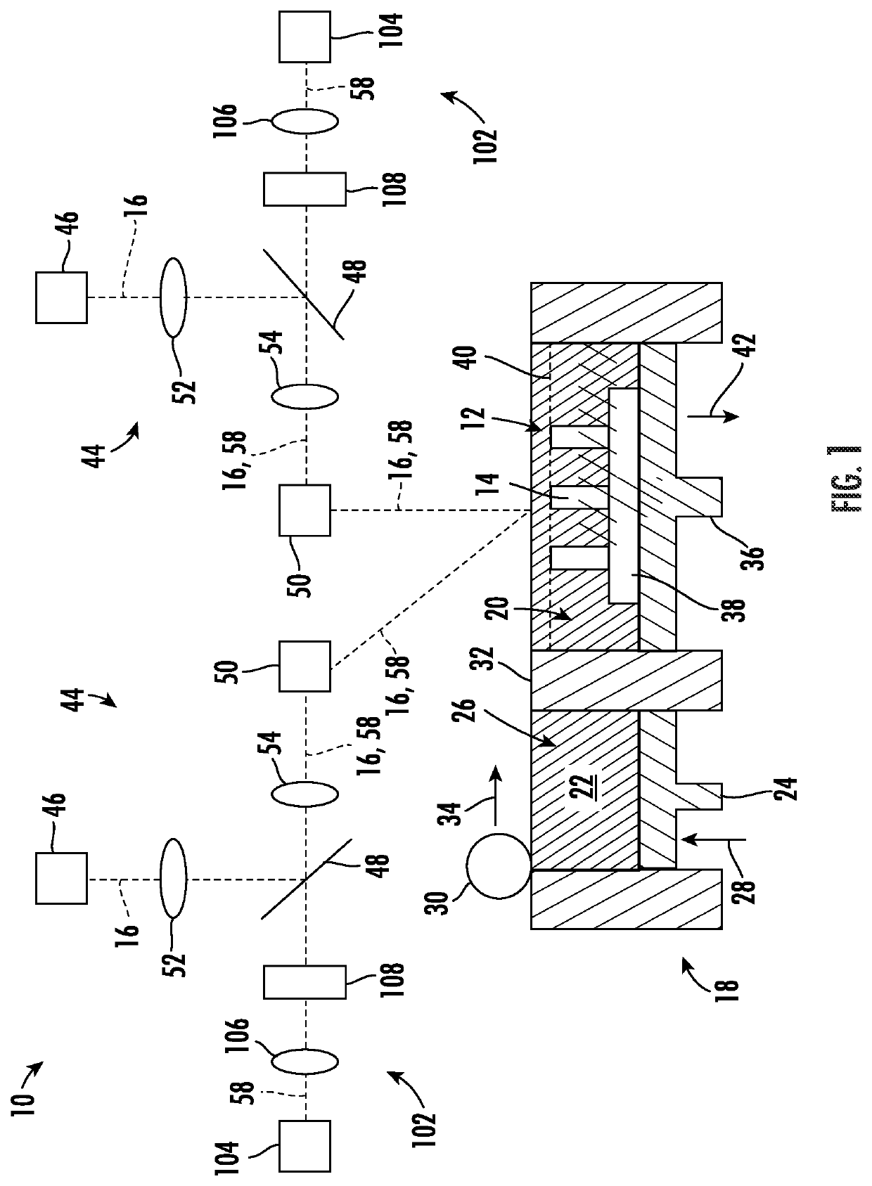
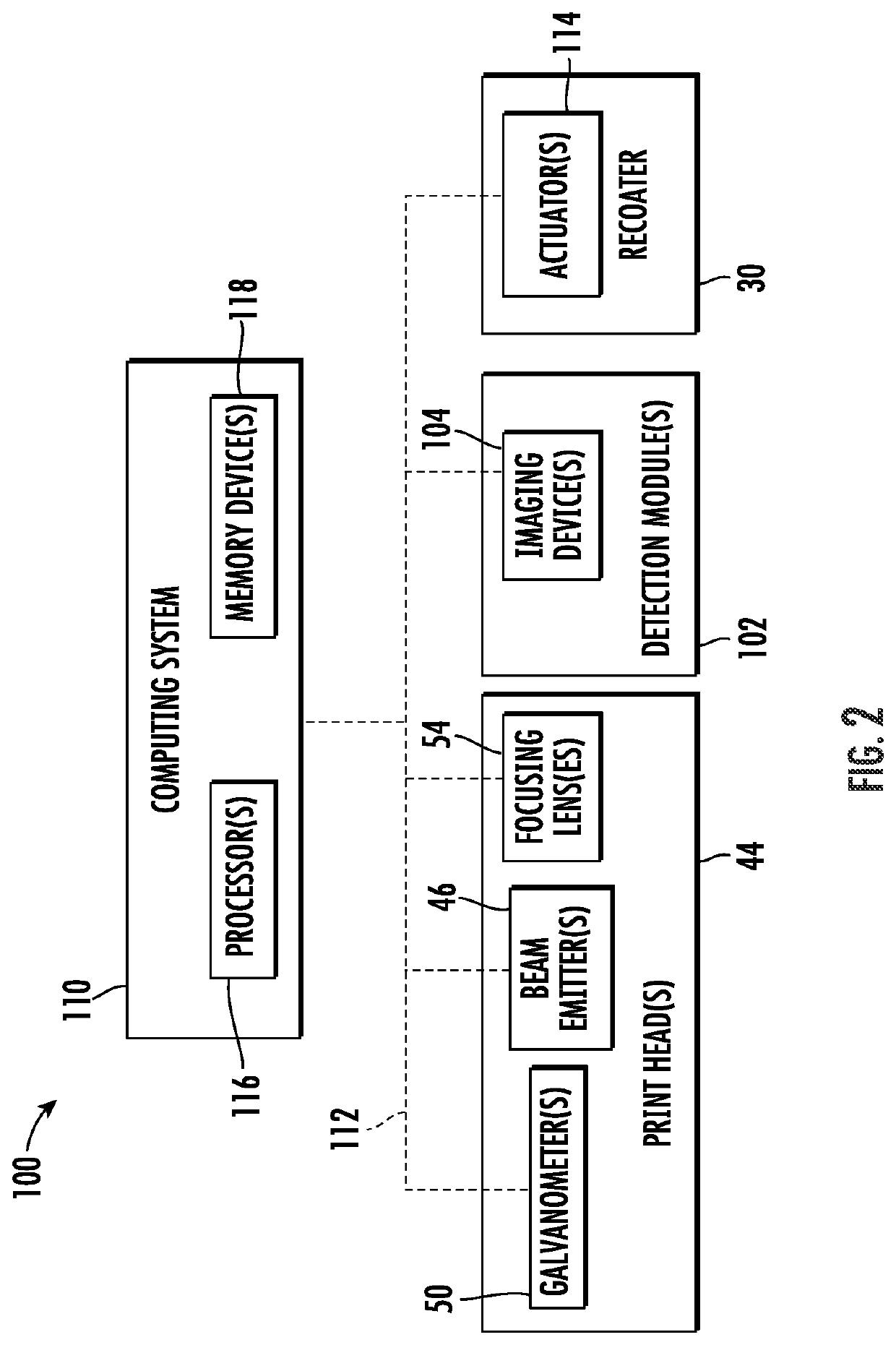
FIELD[0001]The present disclosure generally pertains to systems and methods for additively manufacturing workpieces and, more specifically, to systems and methods for additively printing extension segments on workpieces using an additive manufacturing machine.BACKGROUND[0002]Turbomachines, such as gas turbine engines, include various components that incur wear during operation. For example, a gas turbine engine typically includes numerous compressor blades and turbine blades, which operate in a high-temperature and high-stress environment. As such, the tips of the blades incur wear from rubbing against shrouds, chemical degradation or oxidation from hot gases, fatigue from cyclic loading and unloading, diffusion creep of crystalline lattices, and so forth. Worn blades may, in turn, degrade the performance of the gas turbine engine.[0003]Since it is typically expensive to replace the compressor and turbine blades of a gas turbine engine with new blades, systems and methods for repair...

Claims


Application Information

Patent Timeline
IPC IPC(8): B29C64/153B29C64/209B29C64/245B29C64/268B29C64/393B33Y50/02
CPCB29C64/153B29C64/209B29C64/245B33Y10/00B29C64/393B33Y50/02B29C64/268B22F12/00B22F10/28B22F7/062B22F10/31B22F10/85B22F12/90B22F12/41B33Y30/00B33Y80/00B22F7/08B23P6/007F01D5/005B22F5/04B22F10/36B22F12/45F05D2230/80F05D2230/30Y02P10/25B29L2031/082
Inventor SHI, XIAOLEISHI, JINJIEHAMPSHIRE, JOSEPH EDWARDHOFMANN, DOUGLAS FRANKYANG, PINGHAI
Owner GENERAL ELECTRIC CO
Why Eureka
Try Eureka