Precise lifting method and lifting and reinforcing structure for plant equipment foundation

a plant equipment and lifting method technology, applied in the field of construction lifting, can solve the problems of difficult control of lifting velocity and lifting height of plant equipment, adverse effects on equipment operation, and deformation of backfilling soil layer, so as to improve the lifting precision and reduce the disturbance of surroundings , the effect of controlling the lifting heigh

Active Publication Date: 2022-05-12
BEIJING HENGXIANG HONGYE FOUND REINFORCEMENT TECH CO LTD
View PDF15 Cites 3 Cited by
  • Summary
  • Abstract
  • Description
  • Claims
  • Application Information

AI Technical Summary

Benefits of technology

[0005]A first aspect of the present application is to provide a precise lifting method for plant equipment foundation by providing curtain walls on both sides of the plant equipment for isolation, and then providing a reinforcing body for lifting. The method has advantages of little disturbance to surroundings, controllability of the lifting height and high precision of lifting.

Problems solved by technology

Due to an interspace between the concrete baseplate and the backfilling soil layer and a lack of the denseness of the backfilling soil layer, it fails to meet the design requirements of the foundation bearing capacity and leads to subsidence and deformation of the backfilling soil layer.
Therefore, how to precisely lift the plant equipment and reinforce the backfilling soil layer without negatively affecting the operation of the equipment is a problem to be solved.
In addition, the reinforcing body is arranged under the baseplate to increase the thickness of the foundation, playing a buffering role in the subsequent grouting lifting and preventing a problem that the lifting velocity and the height of the plant equipment are difficult to control during lifting process due to too thin baseplate.

Method used


Image

  • Precise lifting method and lifting and reinforcing structure for plant equipment foundation
  • Precise lifting method and lifting and reinforcing structure for plant equipment foundation
  • Precise lifting method and lifting and reinforcing structure for plant equipment foundation

Examples


Embodiment Construction

[0034]The application is further described in detail below in combination with Figures.

[0035]The present application provides a precise lifting method for plant equipment foundation. A strip shaped plant equipment is taken as an example in the following for explaining, and the plant equipment is hereinafter referred to as equipment. The precise lifting method includes following steps:

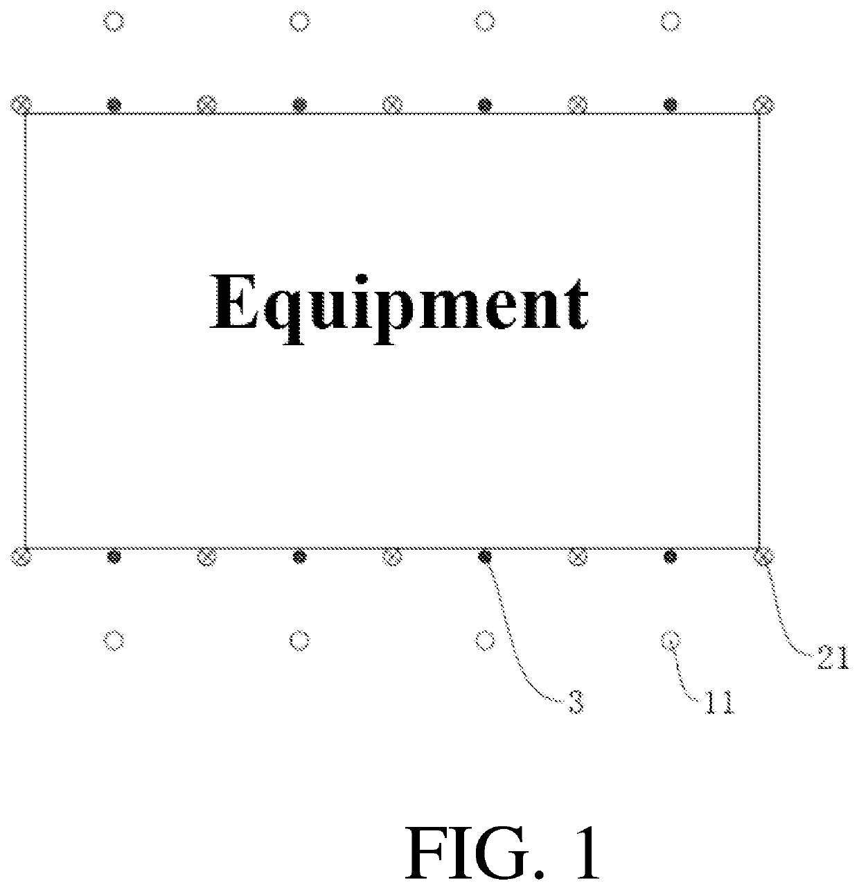
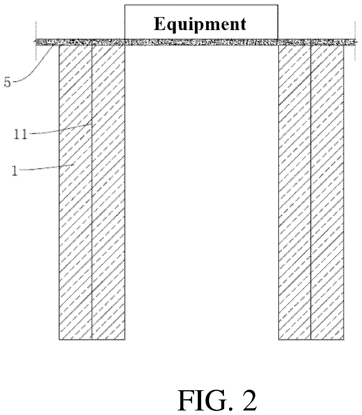
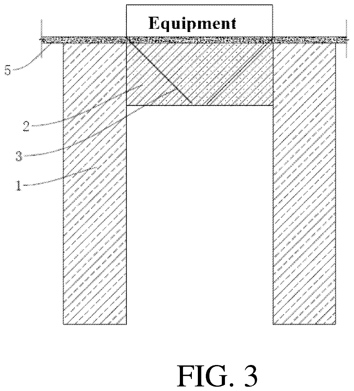
[0036]Step S1, forming a curtain wall 1: referring to FIG. 1 and FIG. 2, curtain holes 11 are drilled downwards in the vertical direction at both sides of the equipment section needed to be lifted, in which the diameter of the curtain hole is 42 mm. A plurality curtain holes 11 are provided evenly spacing along the length direction of the equipment, in which the distance between the adjacent curtain holes 11 is 2-3 m and the distance between the curtain hole 11 and the equipment is 1-2 m.

[0037]Grout is filled into the curtain holes 11, in which the grouting areas overlapped each other, so as to form two...


PUM


Abstract

The present application relates to a precise lifting method and a lifting and reinforcing structure for a plant equipment foundation. The method includes the construction steps of: forming a curtain wall: drilling downwards at two sides of the plant equipment to form curtain holes and grouting the curtain holes, in which the grouting areas overlap each other to form two parallel curtain walls; forming a reinforcing body: drilling grouting holes inclining downwards, grouting the grouting holes to form the reinforcing body attached to a lower surface of a baseplate of the plant equipment foundation among a bottom of the baseplate and two curtain walls; and lifting: drilling lifting holes obliquely downwards to below the bottom of the reinforcing body and between two curtain walls; and conducting pressure grouting to the bottom of the lifting holes and then backward grouting upwards layer by layer.

Description

CROSS-REFERENCE TO RELATED APPLICATION[0001]This application is a continuation of PCT application No. PCT / CN2020 / 107608 filed on Aug. 7, 2020, which claims the priority and benefits of Chinese patent application serial no. 201910736651.X, filed on Aug. 9, 2019. The entirety of the above-mentioned patent applications are hereby incorporated by reference herein and made a part of this specification.TECHNICAL FIELD[0002]The present application relates to a field of a construction lifting and in particular, relates to a precise lifting method and a lifting and reinforcing structure for plant equipment foundation.BACKGROUND ART[0003]At present, a construction of a plant is generally a frame structure, in which a foundation is an independent foundation, relying on columns and the independent foundation for bearing loads. In a conventional precision equipment plant, there is no equipment foundation in the plant and the equipment is directly disposed on a concrete baseplate in the thickness...

Claims


Application Information

Patent Timeline
Patent Type & Authority Applications(United States)
IPC IPC(8): E02D35/00E02D3/12
CPCE02D35/005E02D27/44E02D3/12E02D19/18E02D35/00E02D37/00
Inventor CUI, XUEDONGWU, JIGUANGCUI, TENGYUE
Owner BEIJING HENGXIANG HONGYE FOUND REINFORCEMENT TECH CO LTD
Why Eureka
Try Eureka