
Expansion valve

Pending Publication Date: 2022-05-12
FUJIKOKI CORP
View PDF0 Cites 0 Cited by
  • Summary
  • Abstract
  • Description
  • Claims
  • Application Information

AI Technical Summary

Benefits of technology

The invention is an improved expansion valve that has a simple design and can help reduce noise.

Problems solved by technology

Therefore, a large friction noise tends to occur at a valve portion at the start of the refrigeration cycle system, and therefore, limiting of flow rate of the refrigerant is required as a countermeasure.
Meanwhile, during a stable period in which a certain time has elapsed from the activation of the refrigeration cycle, friction noise becomes small since the liquid density becomes higher compared to when the refrigeration cycle is started.

Method used


Image

  • Expansion valve
  • Expansion valve
  • Expansion valve

Examples


first embodiment

[0030]A general configuration of the expansion valve 10 according to a first embodiment will be described with reference to FIG. 1. FIG. 1 is a schematic cross-sectional view illustrating an example where the expansion valve 10 according to the present embodiment is applied to a refrigerant cycle system 100. In the present embodiment, the expansion valve 10 is connected to a compressor 101, a capacitor 102 and an evaporator 104 that constitute the refrigerant cycle system 100.

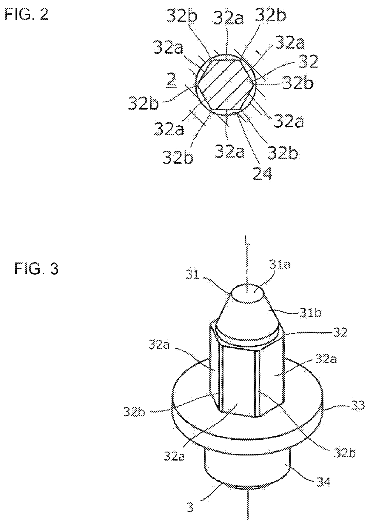
[0031]The expansion valve 10 includes a valve main body 2 equipped with a cylindrical valve chamber VS, the valve body 3, an urging device 4, the actuation rod 5, and a ring spring 6.

[0032]The valve main body 2 includes a first flow channel 21 and a second flow channel 22 in addition to a valve chamber VS. The first flow channel 21 is a supply-side flow channel, for example, and a refrigerant, also referred to as a fluid, is supplied to the valve chamber VS via a supply-side flow channel. The second flow channe...

second embodiment

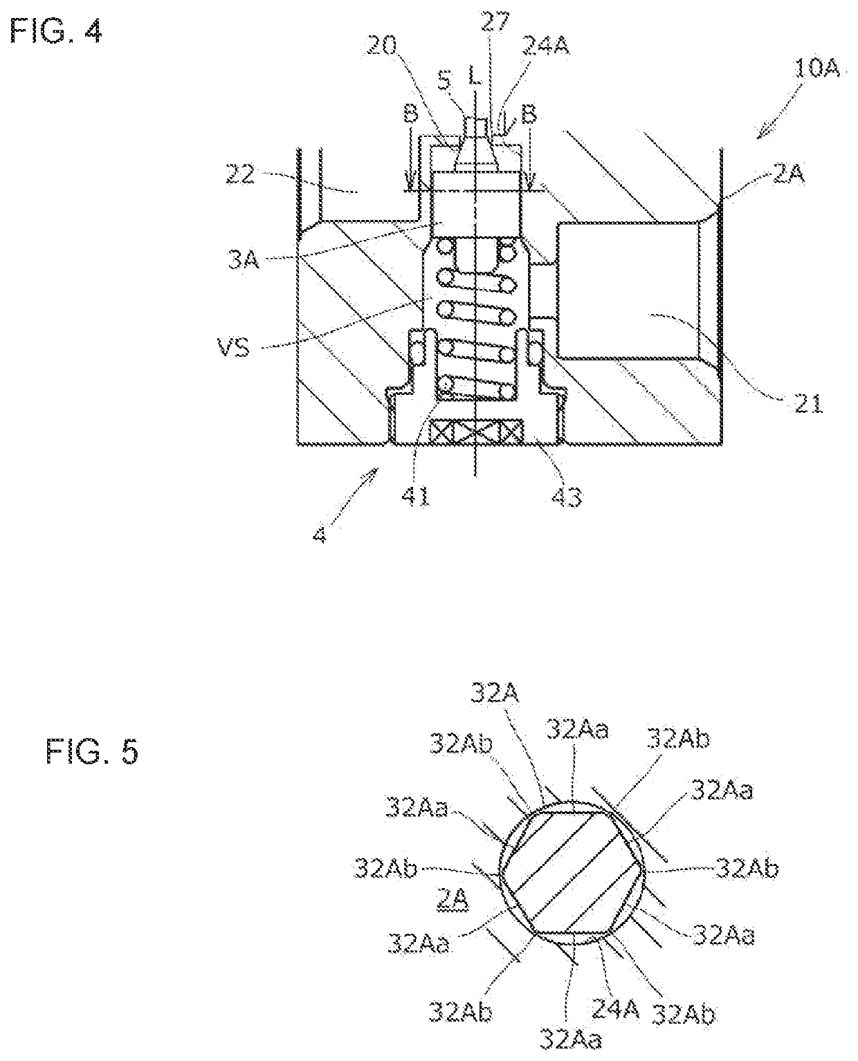
[0061]Next, an expansion valve according to a second embodiment will be described. FIG. 4 is a cross-sectional view illustrating a vicinity of a valve body of an expansion valve 10A in enlarged view. FIG. 5 is a top view of a cross section taken at line B-B of FIG. 4. FIG. 6 is a perspective view of the valve body 3A.

[0062]In FIG. 6, the valve body 3A is formed by consecutively connecting a conical contact portion 31A, a body portion 32A having a hexagonal tubular shape, and an end portion 34A having a cylindrical shape.

[0063]A tapered surface 31Ab of the contact portion 31A is abutted against the valve seat 20. Further, an upper surface 31Aa of the contact portion 31A is a plane surface that is orthogonal to the axis L. An outer circumference of the body portion 32A is composed of six plane surfaces 32Aa and connecting surfaces 32Ab that are formed between adjacent plane surfaces 32a. Each connecting surface 32b can either be a plane surface or a curved surface. The peripheral leng...

third embodiment

[0068]Next, an expansion valve according to a third embodiment will be described. FIG. 7 is a cross-sectional view illustrating a vicinity of a valve body of an expansion valve 10B in enlarged view. FIG. 8 is a top view of the cross section taken at line C-C of FIG. 7. FIG. 9 is a perspective view of a valve body 3B.

[0069]In FIG. 9, the valve body 3B is formed by consecutively connecting a conical contact portion 31B, a body portion 32B having a cylindrical shape, a flange portion 33B having a disk shape, and an end portion 34B having a cylindrical shape.

[0070]A tapered surface 31Bb of the contact portion 31B is abutted against the valve seat 20. Further, an upper surface 31Ba of the contact portion 31B is a plane surface that is orthogonal to the axis L. The length of the body portion 32B should preferably be the same as a maximum diagonal length of an inner wall 24B of the valve chamber VS (or a diameter of the body portion 32B) or greater.

[0071]As illustrated in FIG. 8, the inner...


PUM


Abstract

An improved expansion valve is provided, which has a simple configuration and with which noise can be reduced. An expansion valve includes a valve main body having a valve chamber and a valve seat, a valve body configured to prevent passage of a fluid by being seated on the valve seat and allow passage of the fluid by separating from the valve seat, a coil spring configured to urge the valve body toward the valve seat, and an actuation rod configured to press the valve body toward a direction separating from the valve seat against an urging force applied from the coil spring, wherein the valve chamber includes a cylindrical inner wall being connected to the valve seat, the valve body includes a contact portion configured to be seated on the valve seat and a body portion having a tubular shape facing the inner wall, and the body portion includes connecting surfaces that are slidably in contact with the inner wall and plane surfaces that have a gap provided between the inner wall.

Description

TECHNICAL FIELD[0001]The present invention relates to an expansion valve.BACKGROUND ART[0002]Hitherto, in a refrigeration cycle system adopted in an air conditioner mounted on an automobile, for example, a temperature-sensitive expansion valve that adjusts an amount of a refrigerant passing therethrough according to temperature, with the aim to cut down installation space and piping.[0003]In a general expansion valve, a spherical valve body arranged in a valve chamber is positioned to face a valve seat formed as an opening on the valve chamber. The valve body is supported by a valve body support arranged in the valve chamber and urged toward the valve seat by a coil spring arranged between a spring holding member attached to the valve main body and the valve body support. Then, the valve body is pressed by an actuation rod driven by a power element and moves away from the valve seat to allow passage of a refrigerant. The refrigerant that has passed through a throttle flow channel be...

Claims


Application Information

Patent Timeline
IPC IPC(8): F25B41/31
CPCF25B41/31F25B2500/12F25B41/335F25B2341/0683F25B2500/06F25B2500/03F25B2341/06
Inventor TOMITSUKA, MASAHIROYOKOTA, HIROSHIYANO, TAKAHIRO
Owner FUJIKOKI CORP
Features
  • Generate Ideas
  • Intellectual Property
  • Life Sciences
  • Materials
  • Tech Scout
  • Unparalleled Data Quality
  • Higher Quality Content
  • 60% Fewer Hallucinations
Learn More