Optical film

Pending Publication Date: 2022-05-12
NITTO DENKO CORP
View PDF0 Cites 0 Cited by
  • Summary
  • Abstract
  • Description
  • Claims
  • Application Information

AI Technical Summary

Benefits of technology

[0009]According to the present invention, the optical film, which, despite including a polarizing plate having a recessed portion or

Problems solved by technology

In such case, there is a problem in that the polarizing plate absorbs light to preclude a sufficient quantity of the light from reaching the camera.
However, as a result of the formation of the removed portion, there occurs a problem in terms of process, such as the tearing of the polarizing plate at t

Method used


Image

  • Optical film
  • Optical film

Examples


Example

[0012]Now, embodiments of the present invention are described. However, the present invention is not limited to these embodiments.

A. Outline of Optical Film

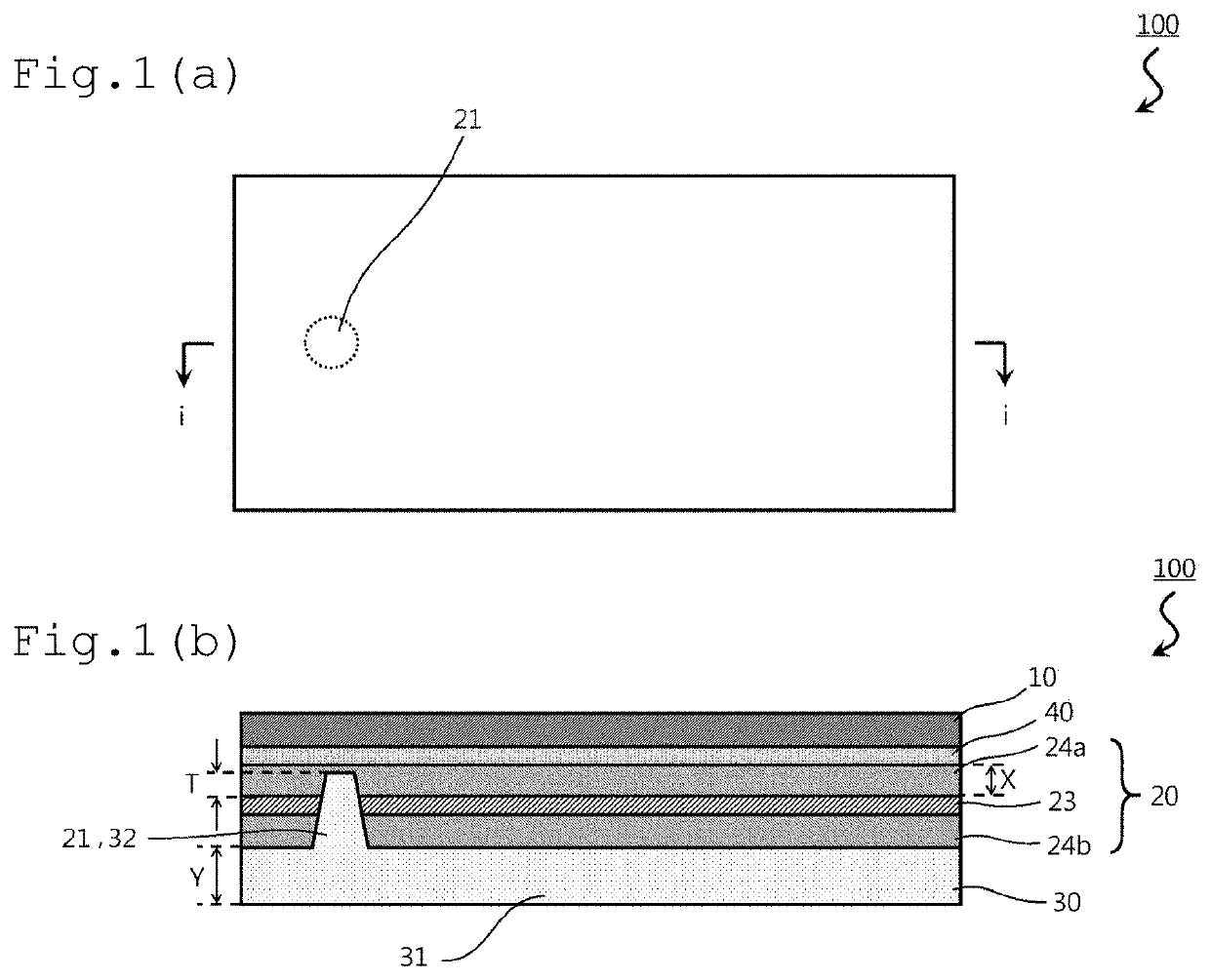
[0013]FIG. 1(a) is a schematic plan view of an optical film according to one embodiment of the present invention, and FIG. 1(b) is a sectional view of the optical film taken along the line i-i of FIG. 1(a). An optical film 100 includes a glass film 10, a polarizing plate 20, and a pressure-sensitive adhesive layer 30 in the stated order. The polarizing plate 20 has a recessed portion 21 that opens on a surface opposite to the glass film 10 (lower surface of the polarizing plate). Part of the pressure-sensitive adhesive layer 30 fills the recessed portion 21. More specifically, the pressure-sensitive adhesive layer 30 fills the recessed portion 21 while being formed so as to be capable of bonding the optical film 100 to any appropriate adherend (e.g., a liquid crystal cell). Herein, for convenience, the glass film side of the opti...


PUM


Abstract

Provided is an optical film, which, despite including a polarizing plate having a recessed portion or a through-hole, is excellent in handleability, is suppressed from causing the strain of the polarizing plate, and shows a small dimensional change owing to an environmental change. The optical film of the present invention includes a glass film, a polarizing plate, and a pressure-sensitive adhesive layer in the stated order, wherein the polarizing plate has a recessed portion that opens on a surface of the polarizing plate opposite to the glass film, or a through-hole, wherein part of the pressure-sensitive adhesive layer fills the recessed portion or the through-hole, and wherein the glass film has a thickness of from 30 μm to 150 μm.

Description

TECHNICAL FIELD[0001]The present invention relates to an optical film.BACKGROUND ART[0002]Some of image display apparatus, such as a laptop personal computer (PC) and a mobile device, are each mounted with a camera. In any such image display apparatus, a configuration in which its outermost surface layer has no step has been required from the viewpoint of a design property, and hence a polarizing plate may be arranged on a viewer side with respect to the built-in camera. In such case, there is a problem in that the polarizing plate absorbs light to preclude a sufficient quantity of the light from reaching the camera. To solve the problem, an investigation has been made on a technology including removing part of the polarizing plate in its thickness direction at a position corresponding to the camera and filling a recessed portion (removed portion) thus produced with an optical pressure-sensitive adhesive (e.g., Patent Literature 1). However, as a result of the formation of the remov...

Claims


Application Information

Patent Timeline
IPC IPC(8): G02B5/30
CPCG02B5/3025G02F1/1335G02B5/3033G02B1/14G02F2202/28B29D11/00788B32B7/023B32B7/12
Inventor MURASHIGE, TAKESHIINAGAKI, JUNICHISATO, KEISUKEKISHI, ATSUSHI
Owner NITTO DENKO CORP
Why Eureka
Try Eureka