Eureka AIR delivers breakthrough ideas for toughest innovation challenges, trusted by R&D personnel around the world.

Ceramic electronic component

Pending Publication Date: 2022-05-12
TDK CORPARATION +1
View PDF0 Cites 0 Cited by
  • Summary
  • Abstract
  • Description
  • Claims
  • Application Information

AI Technical Summary

Benefits of technology

The present invention aims to reduce cracks that occur in the body of ceramic electronic components. This provides a solution to prevent damage to the component and improves its overall quality.

Problems solved by technology

The solder fillet affects the generation of cracks in the ceramic element body.

Method used


Image

  • Ceramic electronic component
  • Ceramic electronic component
  • Ceramic electronic component

Examples


modification example

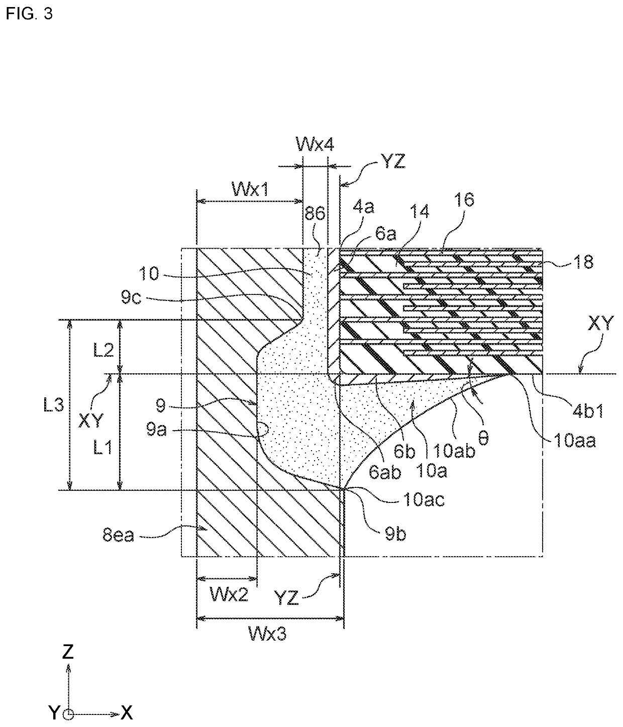
[0105]For example, the lead terminals 8 may have a form as shown in FIG. 5. A second recess 91 is formed on the facing surface Baa of the adjacent part 8a in the lead terminal 81 shown in FIG. 5. The second recess 91 extends along the Z-axis from the upper end to the lower end of the facing surface 8aa. Further, the lower end of the second recess 91 in the Z-axis direction is connected to the first recess 9, and the second recess 91 and the first recess 9 mutually communicate. A crack suppressing effect can be expected even when the lead terminal 81 shown in FIG. 5 is used. In addition, since the lead terminal 81 is used, the amount of solder 10 interposed in the gap 86 between the facing surface Baa and the end-face electrode 6a increases, and the connecting strength of the lead terminal 81 tends to improve.

[0106]Further, according to the lead terminal 8 shown in FIGS. 2 and 3, the upper support part 8ea extends substantially parallel to the Z-axis, but the extension direction of t...


PUM


Abstract

A ceramic electronic component including: a ceramic element body including an end surface extending along a first axis, and a side surface extending along a second axis and intersecting the end surface; an end-face electrode formed on the end surface of the ceramic element body; and a lead terminal connected to the end-face electrode by soldering. The lead terminal includes: an adjacent part overlapping the end-face electrode in a side view from the second axis; and an extension part extending from an end of the adjacent part in a direction away from a plane including the side surface. A first recess is formed at the extension part and is recessed in a direction away from a plane including the end surface, and the first recess exists at a position close to the end of the adjacent part.

Description

BACKGROUND OF THE INVENTION[0001]The invention relates to a ceramic electronic component with lead terminals.[0002]A ceramic electronic component with lead terminals as shown in Patent Document 1 is known as an electronic component mounted on such as a circuit board. According to such ceramic electronic component, it is common to use a solder for connecting the lead terminals to a ceramic element body which terminal electrodes are formed. Specifically, as disclosed in Patent Document 1, soldering of lead terminals is performed by sandwiching a ceramic element body between a pair of lead terminals, and immersing or dipping thereof in a solder bath.[0003]At this time, a fillet is formed between the lead terminal and the terminal electrode by the solder getting wet and spreading. At the end of the ceramic element body contacting the fillet, cracks are likely to occur inside the element body due to shrinkage stress generated during solidification of the solder. The presence of cracks in...

Claims


Application Information

Patent Timeline
IPC IPC(8): H01G4/232H01G4/30H01G4/012H01G4/008
CPCH01G4/2325H01G4/008H01G4/012H01G4/30H01G4/228H01G4/232H01G2/06
Inventor MORI, MASAHIROMASUDA, AKIHIROITO, SHINYAANDO, NORIHISA
Owner TDK CORPARATION
Why Eureka
Eureka Blog
Learn More