Eureka AIR delivers breakthrough ideas for toughest innovation challenges, trusted by R&D personnel around the world.

Repairing method

Inactive Publication Date: 2015-02-12
MITSUBISHI HEAVY IND LTD
View PDF16 Cites 9 Cited by
  • Summary
  • Abstract
  • Description
  • Claims
  • Application Information

AI Technical Summary

Benefits of technology

The patent describes a repairing method for reducing cracks in a base material. The method involves heating the material before adding a laser to the repair area, which helps to prevent the material from cracking during the repair process. This method improves the quality of the repair and reduces the likelihood of failure.

Problems solved by technology

When the TiAl intermetallic compound is mechanically worked, a crack and a break are easily generated therein.
The part made of the TiAl intermetallic compound is typically brittle.
Also, when the same filler material as the base material is used for the build-up welding, a residual stress generated in the build-up welding portion is high, and the ductility is low.
Therefore, the break is easily generated, and a repairing work is difficult.

Method used


Image

  • Repairing method
  • Repairing method
  • Repairing method

Examples


Embodiment Construction

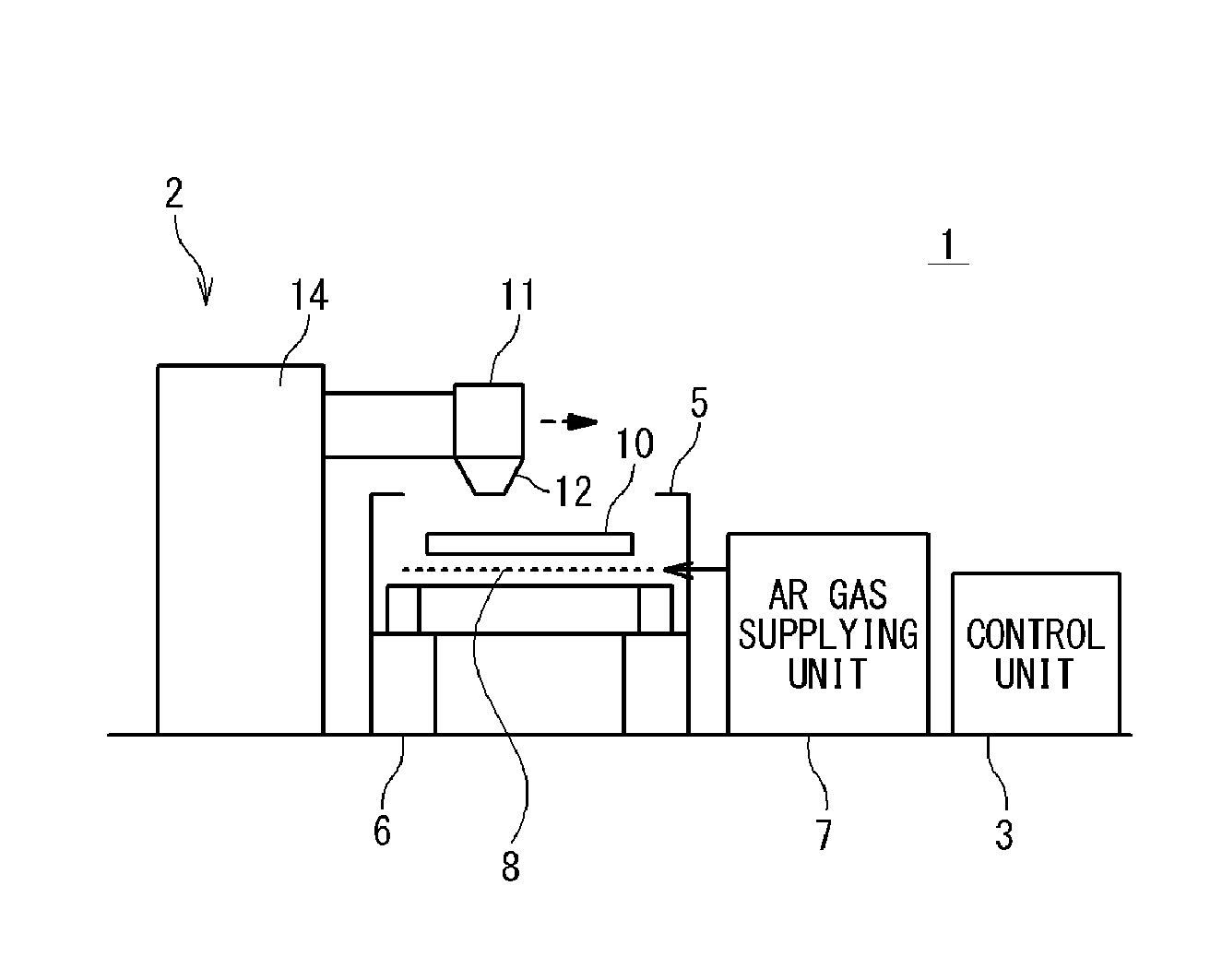
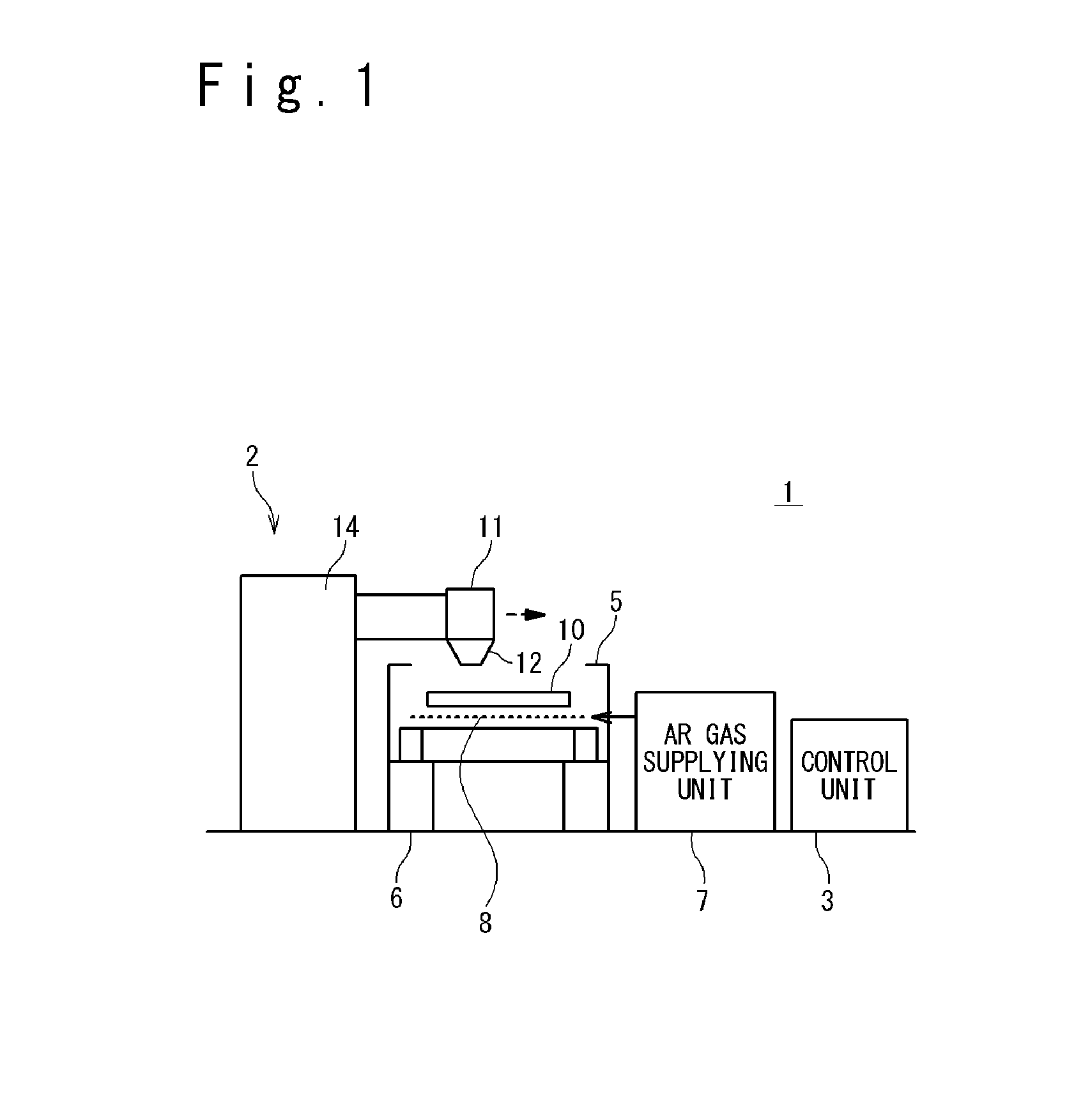
[0033]Hereinafter, a repairing apparatus according to embodiments of the present invention will be described in detail with reference to the attached drawings. A repairing apparatus 1 contains a main section 2 and a control unit 3, as shown in FIG. 1. The main section 2 of the repairing apparatus contains a shield chamber 5, a table 6, an argon gas supplying unit 7 and a heater 8. The shield chamber 5 is formed as a container in which a base material 10 can be accumulated. In the shield chamber 5, an opening is formed in the upper portion to connect the inside of the container and the outside of the container. The table 6 is arranged inside the shield chamber 5 to support the base material 10 so that the base material 10 is held in a predetermined attitude. A proper hole is formed in the lower portion of the shield chamber 5, and the argon gas supplying unit 7 supplies an argon gas through the hole to the inside of the shield chamber 5. The heater 8 heats a heating target with radia...


PUM

PropertyMeasurementUnit
Temperatureaaaaaaaaaa
Particle diameteraaaaaaaaaa

Abstract

A repairing method includes heating a base material by a heater, and irradiating a laser beam to a repair region of the base material by using a laser oscillator unit, after the base material is heated. In the method, generation of a crack and a break can be suppressed, and the repair region can be repaired more appropriately.

Description

CROSS REFERENCE[0001]This application claims a priority on convention based on Japanese Patent Application NO. 2013-166476. The disclosure thereof is incorporated herein by reference.TECHNICAL FIELD[0002]The present invention relates to a repairing method, and more particularly relates to a repairing method used when a defect generated in a base material is repaired.BACKGROUND ART[0003]A TiAl intermetallic compound that contains titanium and aluminum is known. The TiAl intermetallic compound is applied to parts that are required to be high in heat resistance and light in weight. As the parts, parts for a flying vehicle and an aerospace engine are exemplified. When the TiAl intermetallic compound is mechanically worked, a crack and a break are easily generated therein. When the crack and break are generated in the part, a build-up welding is required to be performed on a region where the crack and the break are generated. The part made of the TiAl intermetallic compound is typically ...

Claims


Application Information

Patent Timeline
IPC IPC(8): B23P6/04B23K26/34B23K1/005
CPCB23P6/04B23K26/345B23K1/0056B23K26/0869B23K26/123B23K26/127B23K26/32B23K26/342B23K26/702B23K26/60B23P6/045B23K2103/10B23K2103/14B23K2103/52Y10T29/49728Y10T29/49746
Inventor OGASAHARA, TOMOKONISHIKAWA, KOSUKEHIRAMATSU, NORIYUKIFUKUSHIMA, AKIRA
Owner MITSUBISHI HEAVY IND LTD
Why Eureka
Eureka Blog
Learn More