Eureka AIR delivers breakthrough ideas for toughest innovation challenges, trusted by R&D personnel around the world.

Pilot assemblies and methods for enclosed ground flares and elevated flare stacks

Pending Publication Date: 2022-05-19
SUREFIRE PILOTLESS BURNER SYST LLC
View PDF0 Cites 0 Cited by
  • Summary
  • Abstract
  • Description
  • Claims
  • Application Information

AI Technical Summary

Benefits of technology

This patent describes a pilot assembly for flare stacks that has two lines - a fire path tubing and a pilot tubing. The pilot assembly contains a HSI element located in the fire path tubing at a distance from the pilot nozzle, away from the high temperatures generated by the pilot flame. Flame temperature is monitored using a thermocouple, which is placed in the cooler part of the flame inside the pilot nozzle to improve its durability. This solution overcomes the problem of frequent failure caused by extreme heat exposure in prior art pilot assemblies.

Problems solved by technology

US2012 / 0282555 is attached to the external surface of the pilot nozzle, which exposes the thermocouple to extreme heat and results in frequent failure.

Method used


Image

  • Pilot assemblies and methods for enclosed ground flares and elevated flare stacks
  • Pilot assemblies and methods for enclosed ground flares and elevated flare stacks
  • Pilot assemblies and methods for enclosed ground flares and elevated flare stacks

Examples


Embodiment Construction

[0033]Particular aspects of the invention are described below in considerable detail for the purpose for illustrating its principles and operation. However, various modifications may be made, and the scope of the invention is not limited to the exemplary aspects described.

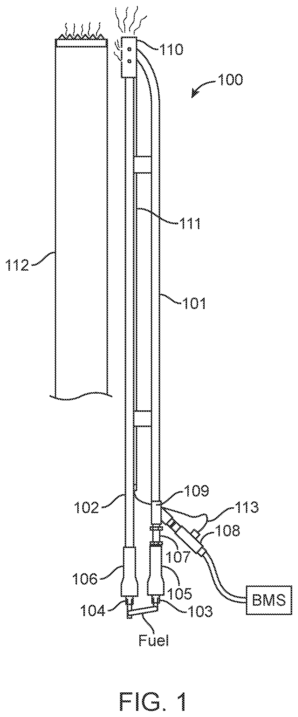
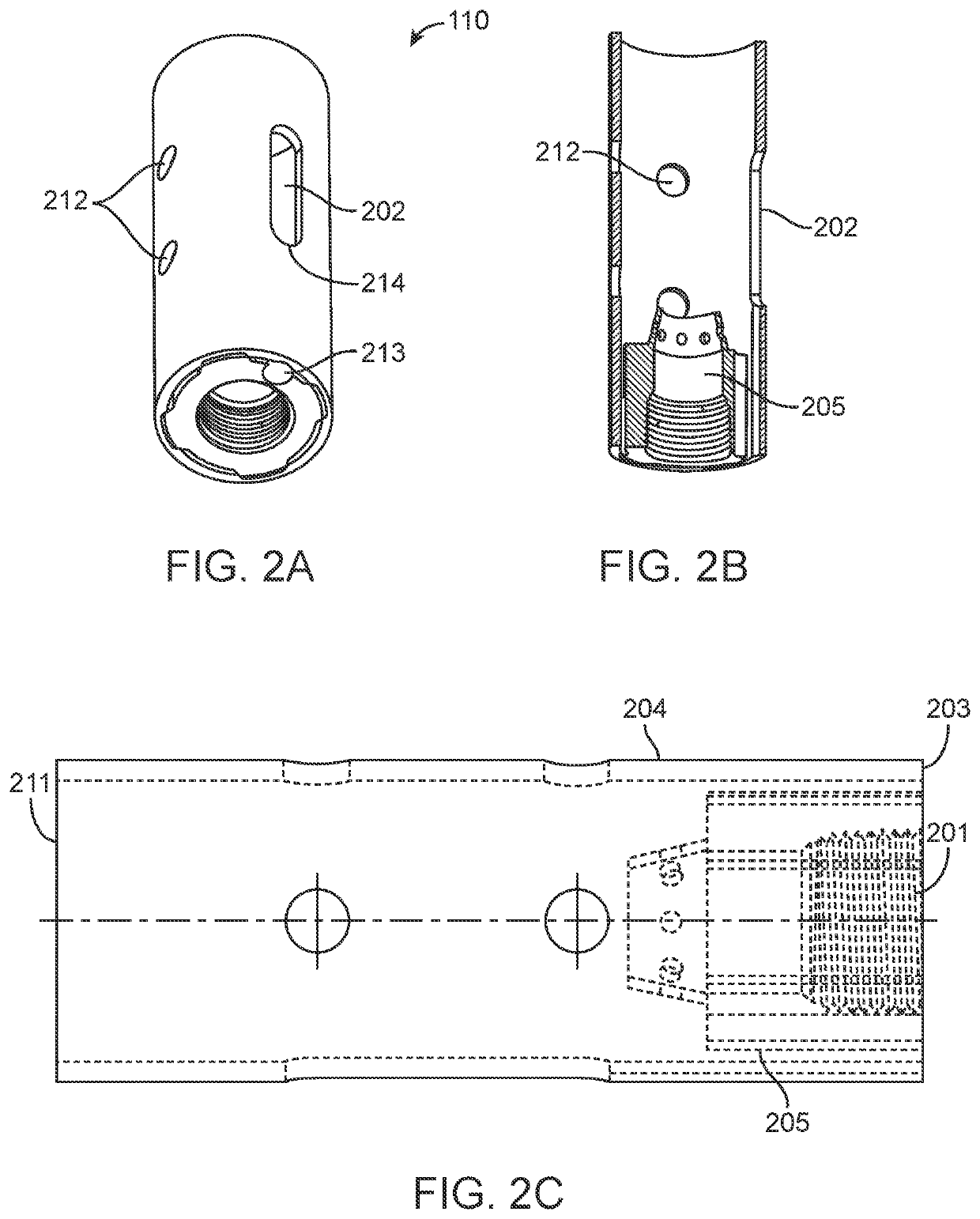
[0034]FIG. 1 illustrates various features of an exemplary pilot assembly 100 for use in elevated flare stacks. The assembly comprises a plurality of tubings, namely, a fire path tubing 101 and a pilot tubing 102 that are preferably disposed substantially parallel to each other. The tubings are generally ¾ in. pipe having outer diameter of about 1.05 in. and made of Type 304 Stainless Steel. Tubings made of other alloys such as Type 316 Stainless Steel, Inconel, and the like may be used. The pilot assembly in turn is disposed substantially parallel to a flare stack 112. The pilot assembly may be between about 2 ft. and about 20 ft. in length, as measured from nozzle end 211 (FIG. 2C) to fuel inlet 103 or 104 and may...


PUM


Abstract

Pilot assemblies comprising a fire path tubing and pilot tubing in fluid communication through a pilot nozzle for burning waste gases in enclosed ground flares and elevated flare stacks are disclosed. A plurality of flame segments is generated using a hot surface ignition element in the fire path tubing and ignites fuel / air mixture flowing through the pilot tubing into a pilot nozzle to produce a reliable pilot flame. Methods for operating the pilot assemblies are disclosed.

Description

CROSS REFERENCE TO RELATED APPLICATIONS[0001]This application is a continuation-in-part of U.S. patent application Ser. No. 16 / 247,553 filed Jan. 14, 2019, which is related to and claims the benefit of and priority to U.S. Provisional Patent Application No. 62 / 619,763, filed Jan. 20, 2018, and titled “Pilot Assemblies and Methods for Elevated Flare Stacks,” which are hereby incorporated by reference in each of their entireties.FIELD[0002]The present invention relates to combustion of waste gases in oil and gas fields using enclosed ground flares and elevated flare stacks. In particular, it relates to pilot assemblies and methods that comprise a fire path tubing for generating a plurality of flame segments using a hot surface ignition element, which then ignites fuel / air mixture in a pilot assembly nozzle to produce a reliable pilot flame.BACKGROUND[0003]Gas flaring is an important unit operation employed during the exploration, production and processing of natural gas and oil from o...

Claims


Application Information

Patent Timeline
IPC IPC(8): F23G7/08F23Q7/10F23Q9/14
CPCF23G7/085F23Q9/14F23Q7/10F23Q7/06
Inventor COOK, RONNIE
Owner SUREFIRE PILOTLESS BURNER SYST LLC
Why Eureka
Eureka Blog
Learn More