Transformer protector with internal fault detector

a transformer protector and fault detector technology, applied in the field of transformer protectors with internal fault detectors, can solve problems such as significant increase of current flow from substations, increase of network load, and faults in distribution networks

Active Publication Date: 2022-05-19
S&C ELECTRIC
View PDF7 Cites 2 Cited by
  • Summary
  • Abstract
  • Description
  • Claims
  • Application Information

AI Technical Summary

Benefits of technology

[0009]The following discussion discloses and describes a fault detection system that includes a recloser configured to perform a reclosing operation in response to detecting overcurrent, where the recloser includes a communications device for receiving communications signals and a controller for operating the recloser. The system also includes a transformer having an outer can that encloses a primary coil and a secondary coil, and a sensor mounted to the can and extending into the can for measuring pressure therein, where the sensor includes an indicator that extends when overpressure is detected. The transformer further includes a radio mounted to the can and coupled to the sensor, where the radio includes a switch coupled to the indicator and a transmitter. When the indicator indicates overpressure in the can it causes a response to prevent the recloser from reclosing.

Problems solved by technology

Periodically, faults occur in the distribution network as a result of various things, such as animals touching the lines, lightning strikes, tree branches falling on the lines, vehicle collisions with utility poles, etc.
Faults may create a short-circuit that increases the load on the network, which may cause the current flow from the substation to significantly increase, for example, many times above the normal current, along the fault path.
This amount of current causes the electrical lines to significantly heat up and possibly melt, and also could cause mechanical damage to various components in the substation and in the network.
For a typical reclosing operation for fault detection tests, about 3-6 cycles or 50 to 100 ms of fault current pass through the recloser before it is opened, but testing on delayed curves can allow fault current to flow for much longer times, which could cause significant stress on various components in the network.
However, it is also desirable not to perform the reclosing operation to test for the fault if the fault is internal to the transformer.
Currently, these types of reclosers and fault interrupters are not able identify that a fault is internal or external to the transformer.

Method used


Image

  • Transformer protector with internal fault detector
  • Transformer protector with internal fault detector

Examples


Embodiment Construction

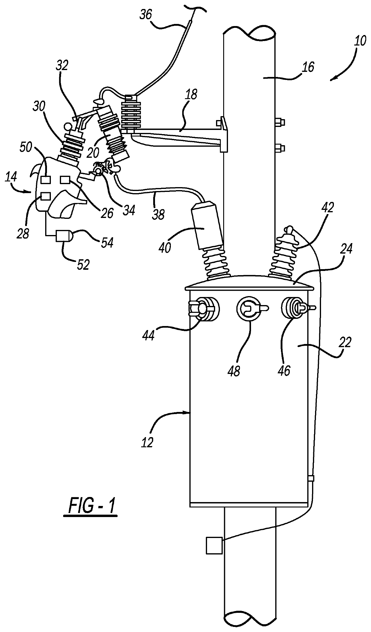
[0014]The following discussion of the embodiments of the disclosure directed to a fault detection system that prevents a recloser from reclosing if a fault is detected internal to a transformer is merely exemplary in nature, and is in no way intended to limit the disclosure or its applications or uses. For example, the discussion below refers to the transformer as being a distribution transformer. However, the fault detection system may be applicable for other types of transformers.

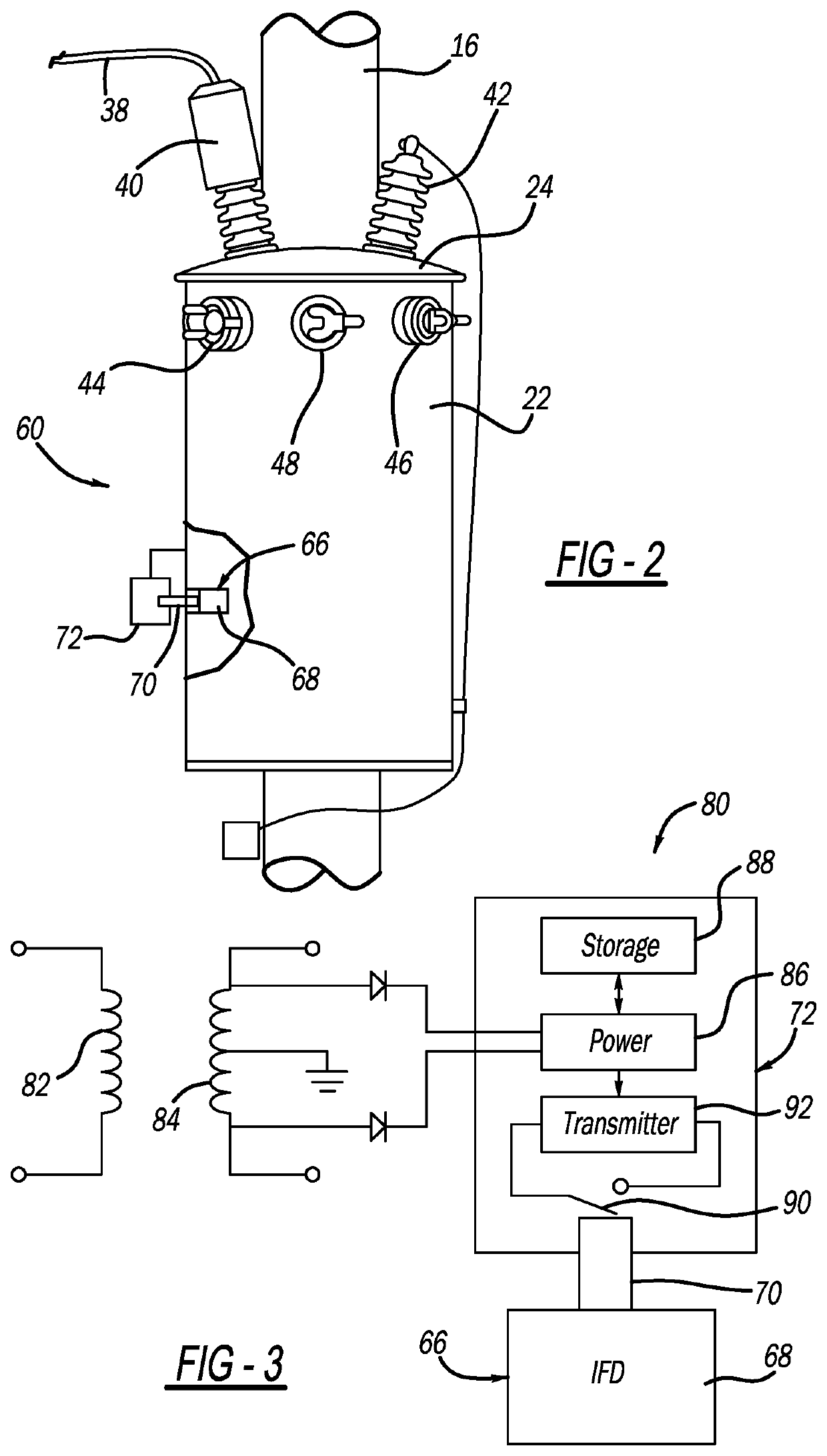
[0015]FIG. 1 is an illustration of a power distribution system 10 including a distribution transformer 12 mounted to a utility pole 16 and a cut-out mounted recloser 14 mounted to the utility pole 16 by a mount 18 and an insulator 20. The transformer 12 includes an outer can 22 having a lid 24 typically filled with oil that houses primary and secondary coils (see FIG. 3). The recloser 14 is intended to represent any reclosing or fault interrupting device of the type discussed above, such as a single phase...


PUM


Abstract

A fault detection system that includes a recloser configured to perform a reclosing operation in response to detecting overcurrent, where the recloser includes a communications device for receiving communications signals. The system also includes a transformer having an outer can, a sensor mounted to the can and extending into the can for measuring pressure therein, where the sensor includes a mechanical indicator that extends when overpressure is detected. The transformer further includes a radio mounted to the can and coupled to the sensor, where the radio includes a switch coupled to the mechanical indicator and a transmitter. When the mechanical indicator extends in response to detecting overpressure in the can it causes the switch to close which causes the transmitter to send a signal that is received by the communications device, which prevents the recloser from reclosing.

Description

CROSS-REFERENCE TO RELATED APPLICATION[0001]This application claims the benefit of priority from the U.S. Provisional Application No. 63 / 115,818, filed on Nov. 19, 2020, the disclosure of which is hereby expressly incorporated herein by reference for all purposes.BACKGROUNDField[0002]This disclosure relates generally to a fault detection system that prevents a recloser from reclosing if a fault is detected that is internal to a transformer and, more particularly, to a fault detection system that prevents a recloser from reclosing if a fault is detected that is internal to a transformer, where the system detects overpressure in the transformer and sends a communications signals to the recloser in response thereto.Discussion of the Related Art[0003]An electrical power distribution network, often referred to as an electrical grid, typically includes a number of power generation plants each having a number of power generators, such as gas turbines, nuclear reactors, coal-fired generator...

Claims


Application Information

Patent Timeline
Patent Type & Authority Applications(United States)
IPC IPC(8): H02H3/06H02H1/00H02H7/04
CPCH02H3/066H02H7/04H02H1/0007H02H1/0061
Inventor TOBIN, THOMAS J.
Owner S&C ELECTRIC
Why Eureka
Try Eureka