Method for transmitting data between a node and a base station in a communication system, and base station and node

a communication system and data transmission technology, applied in the direction of digital transmission, transmission path sub-channel allocation, synchronisation arrangement, etc., can solve the problems of high power consumption of individual consumption meters, inability to incorporate consumption meters into a regional network, and often arisen interference, so as to improve the reception quality

Pending Publication Date: 2022-05-26
DIEHL METERING SYST
View PDF0 Cites 0 Cited by
  • Summary
  • Abstract
  • Description
  • Claims
  • Application Information

AI Technical Summary

Benefits of technology

[0011]The object of the present invention is...

Problems solved by technology

Incorporation of the consumption meters into a regional network is not possible in this case, however.
However, this is expensive, presupposes the installation of mobile radio modules at the consumption meters and has disadvantages regarding the high power consumption at the individual consumption meters.
However, there is the problem that the regularity with which such frequency bands are used for a wide variety of technical devices such as for example garage door controllers, baby monitors, alarm systems, WLAN, Bluetooth, smoke alarms, etc., means that interference can frequently arise.
A particular challenge in this case is that a communication between the data collector and consumption meters requires very exact time synchronization between the oscillators located in the region of the consumption meters and those of the data collector.
Production tolerances, temperature behaviors and ageing mean that such crystals have crystal errors of approximately 10-100 ppm.
In a standard crystal, for example, a crystal error of 50 ppm results in a deviation of 4.3 seconds per day or 26 minutes per annum.
This in turn already results in a deviation in the time synchronization in the event of small temperature...

Method used


Image

  • Method for transmitting data between a node and a base station in a communication system, and base station and node
  • Method for transmitting data between a node and a base station in a communication system, and base station and node
  • Method for transmitting data between a node and a base station in a communication system, and base station and node

Examples


Embodiment Construction

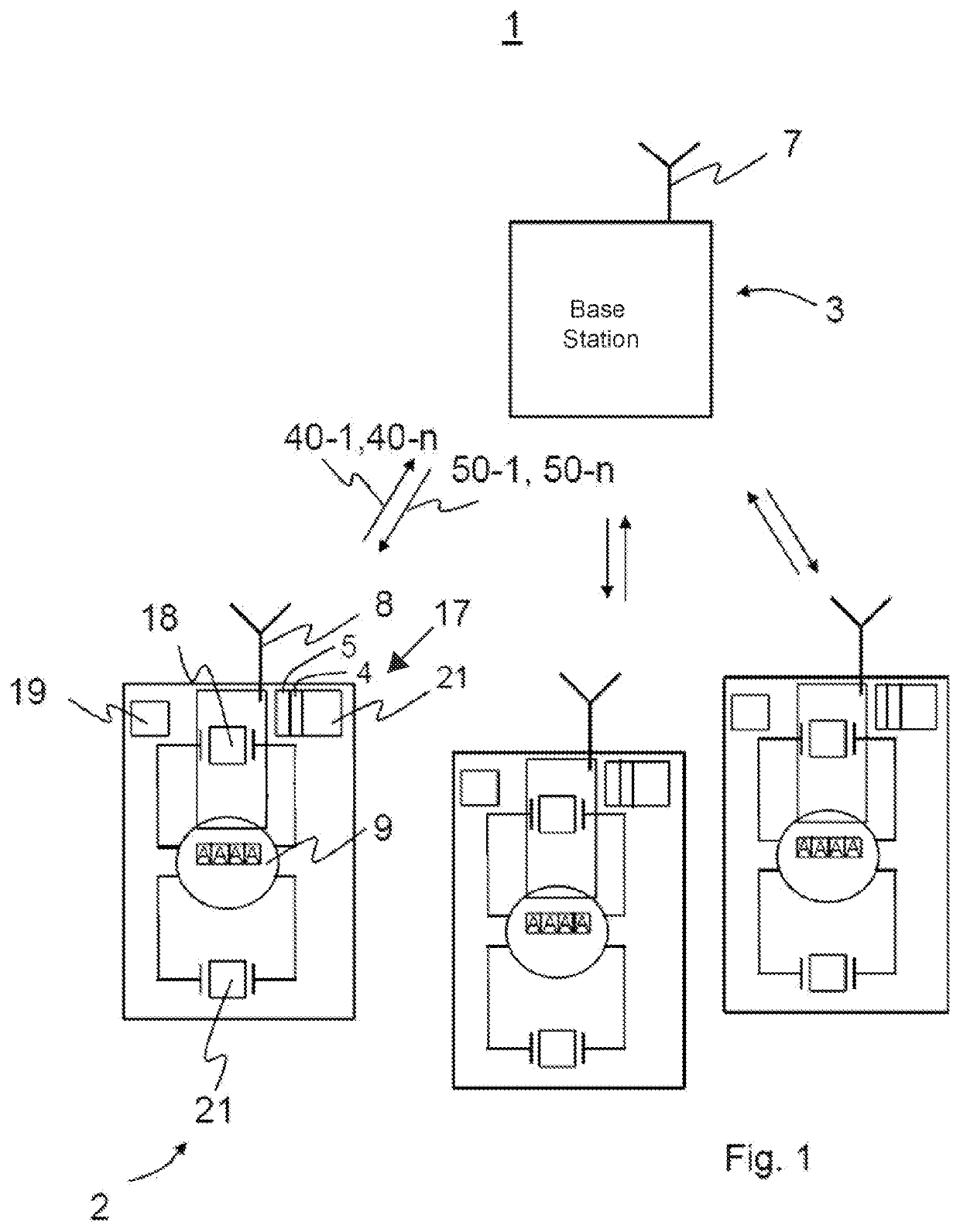
[0040]Referring now to the figures of the drawings in detail and first, particularly to FIG. 1 thereof, there is shown a radio communication system 1, or radio communication network 1, that contains a base station 3, e.g. a so-called data collector, and a plurality of individual, autonomously operated nodes 2. The nodes 2 are for example sensor devices or meters of any type, for example water meters, heat meters, gas meters or electricity meters, or actuators. A common feature of these nodes 2 is that they have a communication module 17 with an antenna 8 and a control and computing unit 19. In addition, each node 2 has a first frequency generator 18 for generating a carrier frequency for the radio transmission and a second frequency generator 21 used for stipulating the times of transmission of data packets 40-1, 40-n in the uplink and for stipulating the reception window for receiving data packets 50-1, 50-n in the downlink. The first frequency generator 18 is an HF (high-frequency...


PUM


Abstract

A method transmits data via radio between a node and a base station with bidirectional radio transmission-based operation. The base station has a communication module with a first frequency transmitter. The node has a communication module with a first frequency transmitter and a second frequency transmitter with a frequency lower than the first frequency transmitter. The communication module of the node is intended to transmit data in the uplink to the communication module of the base station by virtue of a radio telegram being split into two data packets transmitted successively with a temporal spacing. The communication module of the base station transmits data in the downlink to the communication module of the node by virtue of a radio telegram being split into two data packets transmitted successively with a temporal spacing. The transmission time and/or the carrier frequency of at least one of the data packets is corrected.

Description

CROSS-REFERENCE TO RELATED APPLICATION[0001]This application is a continuation, under 35 U.S.C. § 120, of copending International Patent Application PCT / EP2020 / 071799, filed Aug. 3, 2020, which designated the United States; this application also claims the priority, under 35 U.S.C. § 119, of German Patent Application DE 10 2019 005 686.8, filed Aug. 13, 2019; the prior applications are herewith incorporated by reference in their entireties.FIELD AND BACKGROUND OF THE INVENTION[0002]The present invention relates to a method for transmitting data between at least one node and a base station in a communication system using bidirectional radio transmission operation. The invention also relates to a correspondingly prepared node. The invention is particularly suitable for use when recording the consumption of heat or energy, electricity, gas or water by means of autonomous consumption meters.[0003]Nodes of a communication system such as e.g. smart consumption meters are normally associat...

Claims


Application Information

Patent Timeline
IPC IPC(8): H04W56/00H04L5/00H04W72/04
CPCH04W56/0045H04W72/042H04L5/0048H04W56/0035H04W56/0015H04W72/23
Inventor PETKOV, HRISTOLAUTENBACHER, THOMASKAUPPERT, THOMASMZYK, RAPHAEL
Owner DIEHL METERING SYST
Why Eureka
Try Eureka