
Reciprocating pump-type pipe dredging device

Active Publication Date: 2022-06-02
WU KUEI KUN
View PDF3 Cites 0 Cited by
  • Summary
  • Abstract
  • Description
  • Claims
  • Application Information

AI Technical Summary

Benefits of technology

The invention provides a reciprocating pump-type pipe dredging device that solves structural deficiencies of existing dredging devices. The device includes an inflator and a detachable pipe dredging portion. The inflator has a cylinder, an inflator handle, and a first assembly portion with a first opening. The pipe dredging portion has a suction disc and a flexible pipe. The suction disc has a second assembly portion, a disc, and a third assembly portion with a second opening. The flexible pipe includes a pipe and layered flexible ring plates with a third opening. After assembly, the inflator and pipe dredging portion have a continuous passage inside with the plastic ring plates disposed on the outer periphery of the pipe. The inflator and pipe dredging portion are connected with screw threads and the outer diameter of the plastic ring plates taper from an upper layer to a lower layer. The device can be used in different environments or as a dredging effect without the need for a flexible pipe.

Problems solved by technology

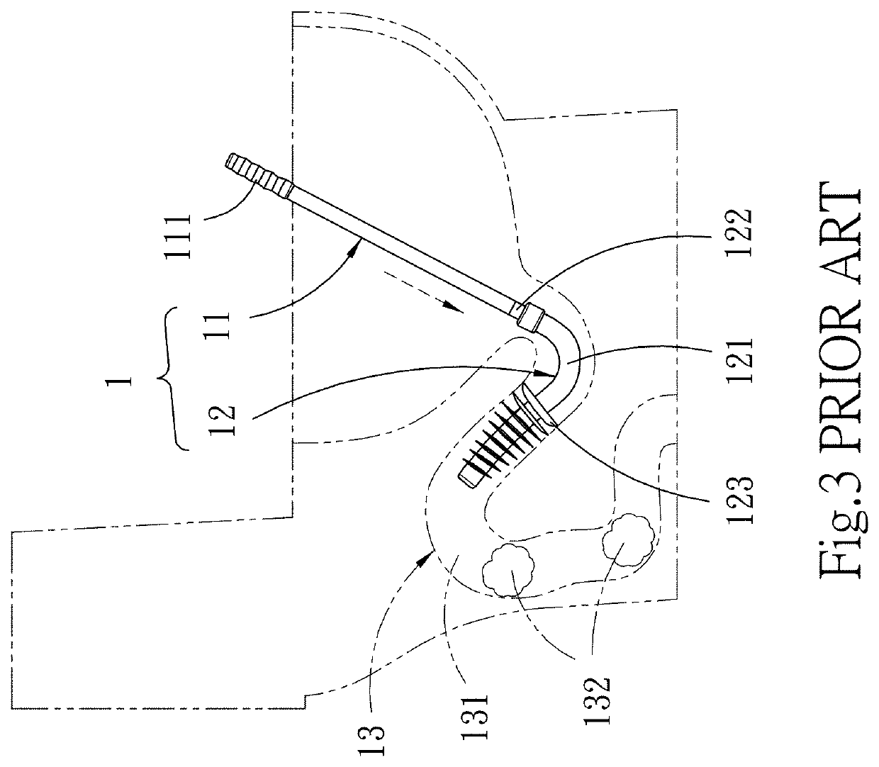
However, a pressure of the dredging device 1 is not strong in view of the repeated motions of the plurality of flexible plates 123 so that a pressure for pushing the blockages 132 blocked at a deepest part of the bent pipe 131 may be too small, consequently, the drainage pipeline 13 and the bent pipe 131 cannot be smoothly dredged.
In addition, since the plurality of flexible plates 123 are not tightly attached to an inner wall of the bent pipe 131, the user cannot pressurize smoothly by holding the grip 111 with a hand to perform repeated motions, and thus the dredging device 1 is extremely laborious and time-consuming in use.
The dredging device 2 will not only cause insufficient air pressure of repetitive motions of the inflator 21, but also cannot smoothly pressurize and dredge the blockages 232 inside the drainage pipeline 23.

Method used


Image

  • Reciprocating pump-type pipe dredging device
  • Reciprocating pump-type pipe dredging device
  • Reciprocating pump-type pipe dredging device

Examples


Embodiment Construction

[0024]The detailed description and technical contents of the invention are described below with reference to the drawings.

[0025]Please refer to FIG. 6, FIG. 7 and FIG. 8 in conjunction with FIG. 9 and FIG. 10. The invention provides a reciprocating pump-type pipe dredging device 3 which comprises an inflator 4 and a pipe dredging portion 5 detachably assembled with the inflator 4. The inflator 4 includes a cylinder 41 with a hollow 411, an inflator handle 42 connected to one end of the cylinder 41 to push air into the hollow 411 of the cylinder 41, and a first assembly portion 43 disposed at one end of the cylinder 41 opposite to the inflator handle 42. The inflator handle 42 includes a push rod 421 connected to one end of the inflator handle 42 and penetrated into the hollow 411 of the cylinder 41, and a plug 422 connected to one end of the push rod 421 opposite to the inflator handle 42. The first assembly portion 43 is provided with a first opening 431 communicating with the holl...


PUM


Abstract

A reciprocating pump-type pipe dredging device comprises an inflator and a pipe dredging portion detachably assembled with the inflator. The inflator includes a cylinder, an inflator handle and a first assembly portion. The pipe dredging portion includes a suction disc and a flexible pipe. The suction disc includes a second assembly portion joined with the first assembly portion, a disc connected to one end of the second assembly portion, and a third assembly portion extending toward an inner top end of the disc and corresponding to the second assembly portion. The flexible pipe includes a pipe and a plurality of layered flexible ring plates. One end of the pipe is provided with a fourth assembly portion joined with the third assembly portion, and the inflator and the pipe dredging portion are formed a continuous passage thereinside after assembling.

Description

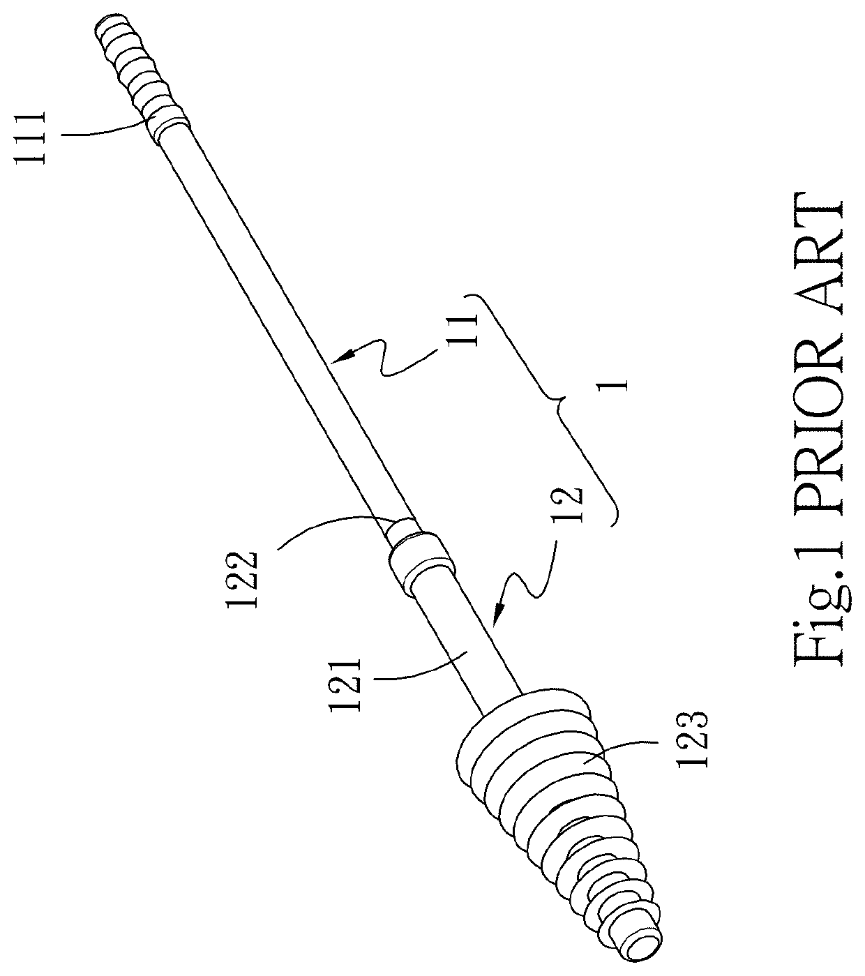
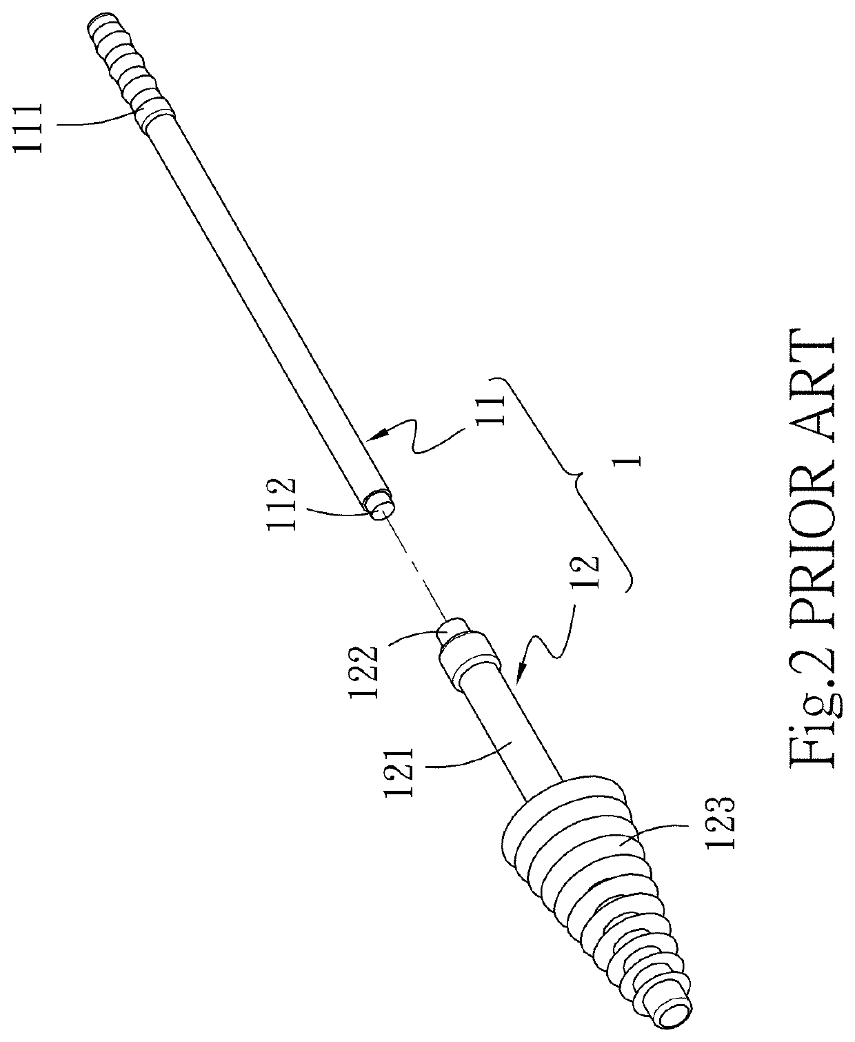
FIELD OF THE INVENTION[0001]The invention relates to a pipe cleaner, and more particularly to a reciprocating pump-type pipe dredging device.BACKGROUND OF THE INVENTION[0002]As shown in FIG. 1, FIG. 2 and FIG. 3, a drainage pipeline 13 is generally provided with a bent pipe 131 in different environments. The drainage pipeline 13 is in a toilet as an example, when the bent pipe 131 of the drainage pipeline 13 in the toilet is blocked by blockages 132 and cannot drain water normally. In order to tackle the blockage, users use a toilet and pipeline dredging washer disclosed by Chinese Publication No. CN 204662597 U, wherein a dredging device 1 is used to dredge the drainage pipeline 13. The dredging device 1 includes a flexible rod 11 and a dredge head 12. The flexible rod 11 includes a grip 111 and a first embedding portion 112 opposite to one end of the grip 111. The grip 111 is provided for a user to hold with a hand and manipulate the flexible rod 11. The dredge head 12 includes a ...

Claims


Application Information

Patent Timeline
IPC IPC(8): E03C1/308
CPCE03C1/308E03D9/00
Inventor WU, KUEI-KUN
Owner WU KUEI KUN
Learn More