Optical Input Devices

a technology of input device and input input, which is applied in the field of optical input device, can solve the problems of less desirable haptic or tactile feedback, less tactile feedback, and less user experience, and achieve the effect of cost-effective and reliable tactile, effective and pleasing user experien

Active Publication Date: 2022-06-02
T PHY LTD
View PDF33 Cites 0 Cited by
  • Summary
  • Abstract
  • Description
  • Claims
  • Application Information

AI Technical Summary

Benefits of technology

[0005]It is an object of aspects of the present invention to address at least some of these issues and provide a cost-effective and reliable tactile device or group of tactile devices, using optical technology, which can be placed anywhere over an existing display without significantly obscuring the display in order to provide a more effective and pleasing user experience, and allow the full benefit of the display both around and / or inside the device itself. The device could be used in any electrical / electronic system where some form of tactile input is required, such as the control panel on white goods or home controllers etc. The device could also be used in conjunction with or as part of a touch panel or screen providing a hybrid touch sensitive and tactile device interface.
[0006]The tactile devices described herein are based on optical techniques and as such do not require any visible communication or power supply paths which could obstruct the useable area and appearance of the display behind the device. Also, the tactile devices could be efficiently used in conjunction with an optical touch screen technology to provide a hybrid tactile input device and touch sensitive interface capability.

Problems solved by technology

However, the touch screen itself provides little to the user in terms of tactile feedback.
In certain types of general use electronic devices such as mobile phones or tablets, the need for haptic or tactile feedback is less desirable than the advantages of complete flexibility and uniformity in the display / touch screen.
However, in applications where the use of the touch screen / panel is much more specific in nature or even dedicated to a single set of tasks such as in the controlling of electrical / electronic appliances, machines or test equipment, it is often desirable to provide some form of tactile feedback for the user, where full configurability of the display may not be as highly sought after.
However, these approaches are expensive and come with their own specific challenges and drawbacks, in terms of not only operation and fabrication but also the degree of flexibility with respect to user customisation, e.g. number, size and location of holes etc.

Method used


Image

  • Optical Input Devices
  • Optical Input Devices
  • Optical Input Devices

Examples


Embodiment Construction

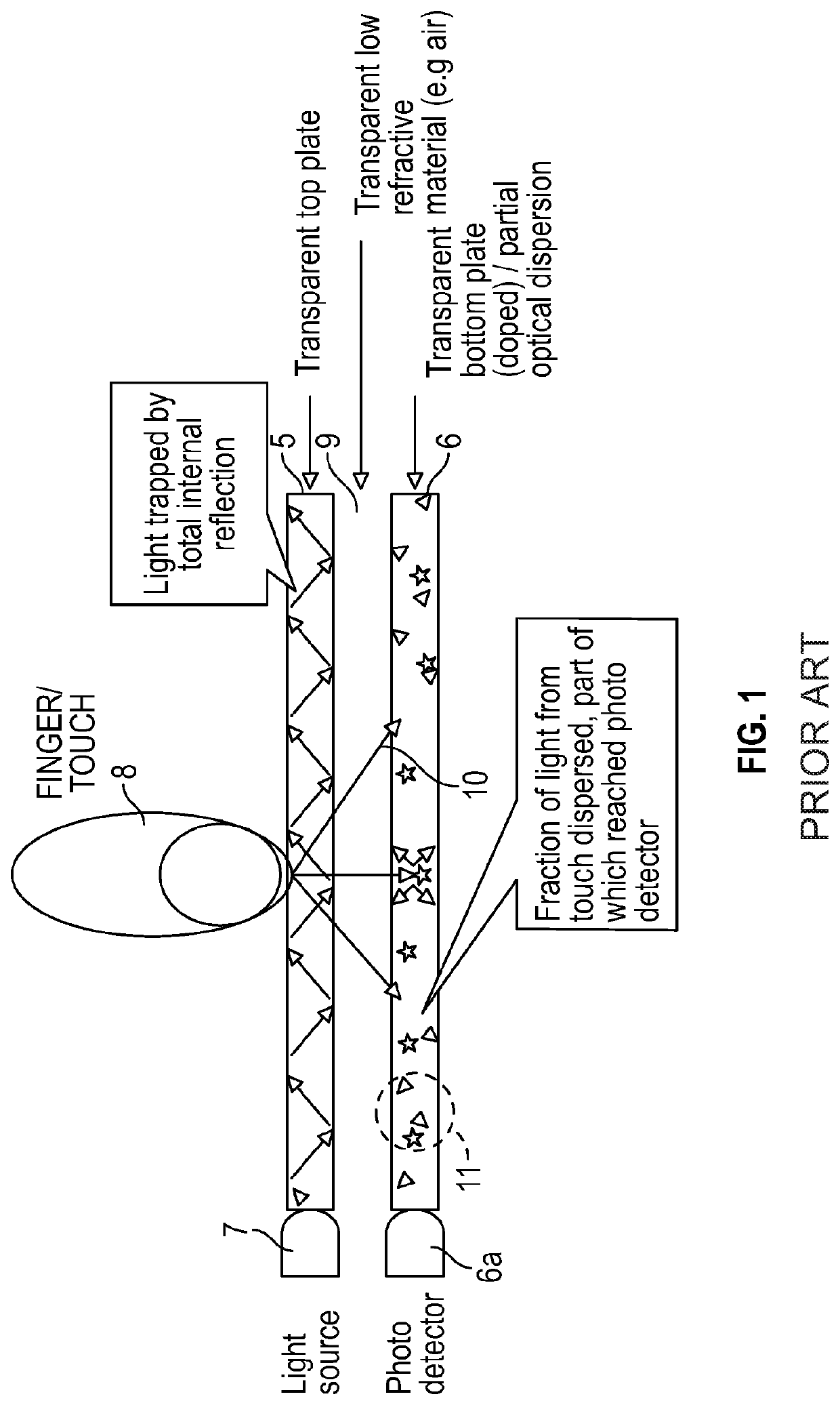
[0040]The underlying technology will now be explained with reference to FIG. 1 of the drawings, in which there is shown an exemplary embodiment of a known screen which may be suitable for use with the present invention. Optically clear plates 5, 6 are separated by a lower refractive index gap 9. The top plate 5 is substantially rectangular in shape and surrounded by a plurality of light sources 7. These sources may be specifically LED light sources 7, but may be any suitable light source as is known in the art (OLED, laser, etc). The light sources 7 inject frequency modulated light evenly at a predetermined angle. This angle is such that the light is contained within the top plate by Total Internal Reflection (TIR). The specific angle required for TIR to occur is determined by the material used to create the top plate 5, and is known as the ‘critical angle’. This can be easily calculated using Snell's Law if the refractive indexes of the top plate 5 and the lower refractive index ga...


PUM

PropertyMeasurementUnit
refractive index gapaaaaaaaaaa
refractive indexaaaaaaaaaa

Abstract

An optical input device includes at least one optically clear plate having at least one light source positioned at a peripheral edge thereof and arranged and configured to transmit frequency modulated light into the optically clear plate along its planar length at an angle such that the modulated light is contained within the plate via total internal reflection thereof. At least one photodetector is configured to receive some or all of the modulated light. A least one input mechanism is embedded within the optically clear plate and is mechanically moveable relative thereto. A processing module receives signals from the photodetector and generates data representative of information to be displayed on a display screen. Both mechanical movement of the input mechanism relative to the optically clear plate and the application of pressure to the clear plate generate respective changes in the modulated light received by the photodetector. A change in the modulated light received by the photodetector causes the processing module to generate data representative of a change in information to be displayed on the display screen.

Description

CROSS REFERENCE TO RELATED APPLICATIONS[0001]The present application is a continuation of U.S. patent application Ser. No. 16 / 514,260, filed Jul. 17, 2019, which is a continuation-in-part of PCT / GB2018 / 050119, filed Jan. 17, 2018, which claims priority to GB 1700809.5, filed Jan. 17, 2017, the subject matter of each of which is hereby incorporated by reference in its entirety.BACKGROUND OF THE INVENTION1. Field of the Invention[0002]This invention relates generally to optical-input devices for tactile user interaction with touch-sensitive display screens, more specifically, though not necessarily exclusively to optical tactile input devices such as rotary dials, switches, sliders, joysticks, pressure pads etc. or any combination thereof (hence forth referred to as tactile devices), which can be mounted into a clear plate and positioned in front of an optical display screen, such as but not restricted to an LCD or OLED display, in such a way that the tactile device can provide input ...

Claims


Application Information

Patent Timeline
Patent Type & Authority Applications(United States)
IPC IPC(8): G06F3/042G06F3/02G06F3/03G06F3/0362
CPCG06F3/0421G06F3/02G06F2203/04109G06F3/0362G06F3/0312G06F3/0428G06F3/0325
Inventor LOMAS, DAVID
Owner T PHY LTD
Why Eureka
Try Eureka