Eureka AIR delivers breakthrough ideas for toughest innovation challenges, trusted by R&D personnel around the world.

Electronic brake system

Pending Publication Date: 2022-06-09
HL MANDO CORP
View PDF0 Cites 0 Cited by
  • Summary
  • Abstract
  • Description
  • Claims
  • Application Information

AI Technical Summary

Benefits of technology

The electronic brake system described in this patent can improve the stability and performance of vehicles in various driving situations. It can enhance the operational stability of products, improve their assembly and productivity, reduce manufacturing costs, and decrease the number of components and size of the system.

Problems solved by technology

As described above, since the electronic brake system electrically operates and is controlled, complicated and various braking functions may be performed.
However, when a technical malfunction occurs in application components, hydraulic pressure required for braking is not stably generated, which may threaten the safety of passengers.
Accordingly, when an element is broken or out of control, the electronic brake system enters a fallback mode which is an abnormal operation mode, and in this case, a driver's brake pedal operation is required to be directly linked to the wheel cylinders.
That is, in the abnormal operation mode of the electronic brake system, when the driver applies a pedal effort to the brake pedal, hydraulic pressure required for braking is required to be immediately generated and transmitted directly to the wheel cylinders.
However, in a conventional electronic brake system, since braking of a vehicle depends entirely on a driver's pedal effort in the fallback mode, movement of the vehicle may become unstable.
Also, an immediate response to a variety of driving situations may not be made, resulting in an increase in safety accidents.

Method used


Image

  • Electronic brake system
  • Electronic brake system
  • Electronic brake system

Examples


Embodiment Construction

[0034]Hereinafter, embodiments of the present disclosure will be described in detail with reference to the accompanying drawings. The following embodiments are provided to fully convey the spirit of the disclosure to a person having ordinary skill in the art to which the present disclosure belongs. The disclosure is not limited to the embodiments shown herein but may be embodied in other forms. The drawings are not intended to limit the scope of the disclosure in any way, and the size of components may be exaggerated for clarity of illustration.

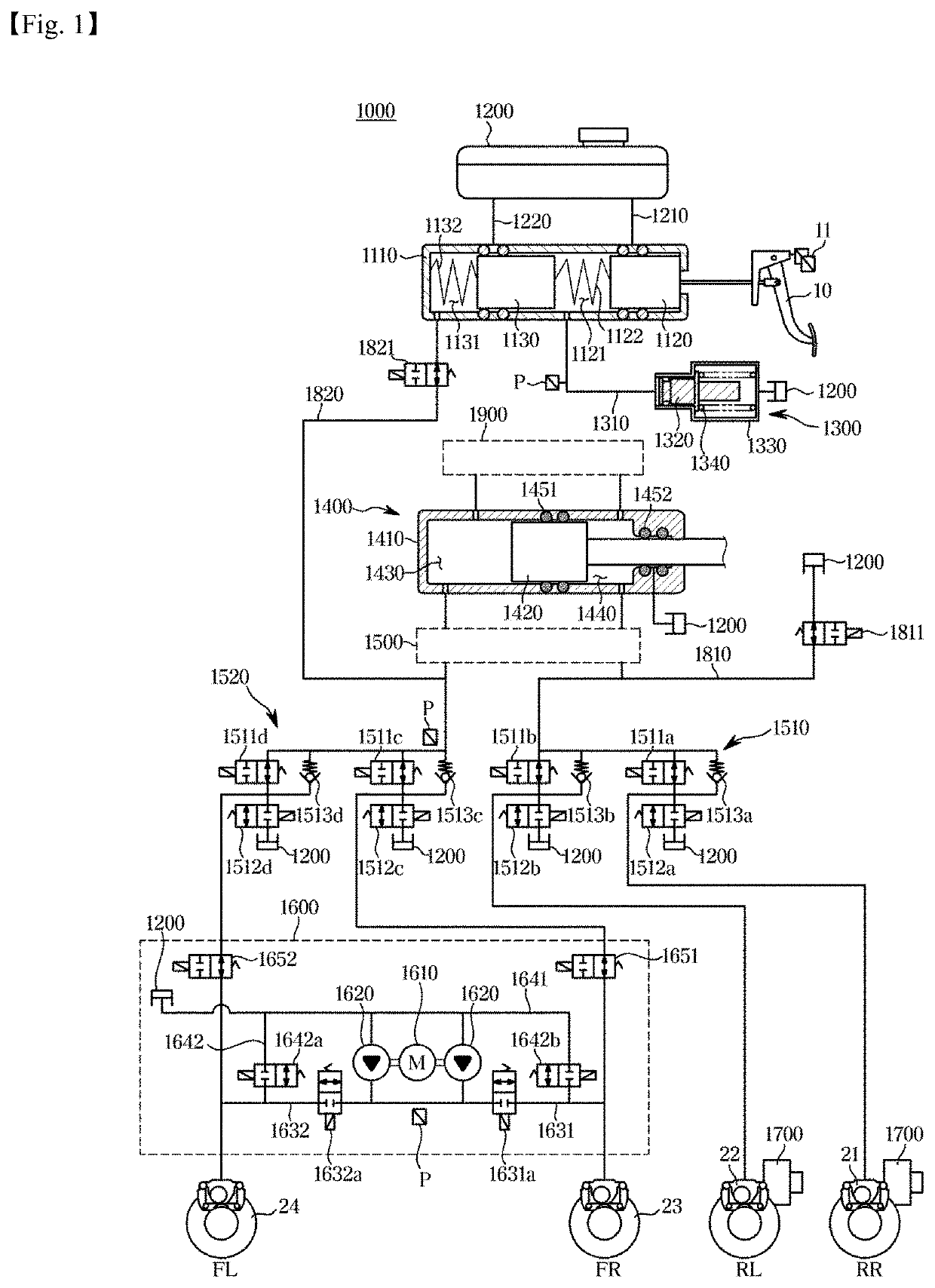
[0035]FIG. 1 is a hydraulic circuit diagram illustrating an electronic brake system 1000 according to an embodiment of the disclosure.

[0036]Referring to FIG. 1, according to an embodiment of the disclosure, the electronic brake system 1000 includes a reservoir 1200, a master cylinder 1100, a pedal simulator 1300, a hydraulic pressure supply device 1400, a hydraulic control unit 1500, a hydraulic auxiliary device 1600, a pair of actuators 1700...


PUM


Abstract

Provided is an electronic brake system. The electronic brake system according to an embodiment of the disclosure includes a reservoir configured to store a pressing medium; a master cylinder connected to a brake pedal; a pedal simulator connected to the master cylinder; a hydraulic pressure supply device configured to generate hydraulic pressure by operating a hydraulic piston by an electrical signal output corresponding to a displacement of the brake pedal; a hydraulic control unit comprising a first hydraulic circuit and a second hydraulic circuit, and configured to control hydraulic pressure transmitted to the first hydraulic circuit and the second hydraulic circuit, the first hydraulic circuit including a first wheel cylinder and a second wheel cylinder, the second hydraulic circuit including a third wheel cylinder and a fourth wheel cylinder.

Description

TECHNICAL FIELD[0001]The disclosure relates to an electronic brake system, and more specifically, to an electronic brake system that generates braking force using an electrical signal corresponding to a displacement of a brake pedal.BACKGROUND ART[0002]A brake system for braking of a vehicle is essentially mounted to a vehicle, and a variety of systems have been recently proposed for safety of drivers and passengers.[0003]In a conventional brake system, when a driver operates a brake pedal, hydraulic pressure for braking is supplied to wheel cylinders using a booster mechanically connected to the brake pedal. Due to the high market demand for various brake functions, however, an electronic brake system provided with a hydraulic pressure supply device has recently come into widespread use. Once a driver operates a brake pedal, the hydraulic pressure supply device of the electronic brake system senses a displacement of the brake pedal through a pedal displacement sensor, and receives ...

Claims


Application Information

Patent Timeline
IPC IPC(8): B60T8/94B60T7/04B60T8/32B60T13/14B60T13/74B60T13/16B60T13/68B60T8/40
CPCB60T8/94B60T7/042B60T8/326B60T13/142B60T13/148B60T13/745B60T2270/404B60T13/686B60T8/409B60T13/741B60T2270/82B60T2270/402B60T13/168B60T8/4081B60T13/146B60T13/662B60T8/4009B60Y2400/81
Inventor KIM, JIN SEOK
Owner HL MANDO CORP
Why Eureka
Eureka Blog
Learn More