

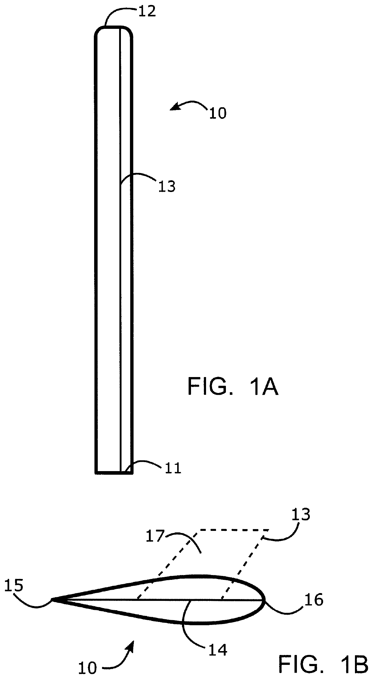
Rotor Blades Of A Lift Rotor
- Summary
- Abstract
- Description
- Claims
- Application Information
AI Technical Summary
Benefits of technology
Problems solved by technology
Method used
Image

Examples
Embodiment Construction
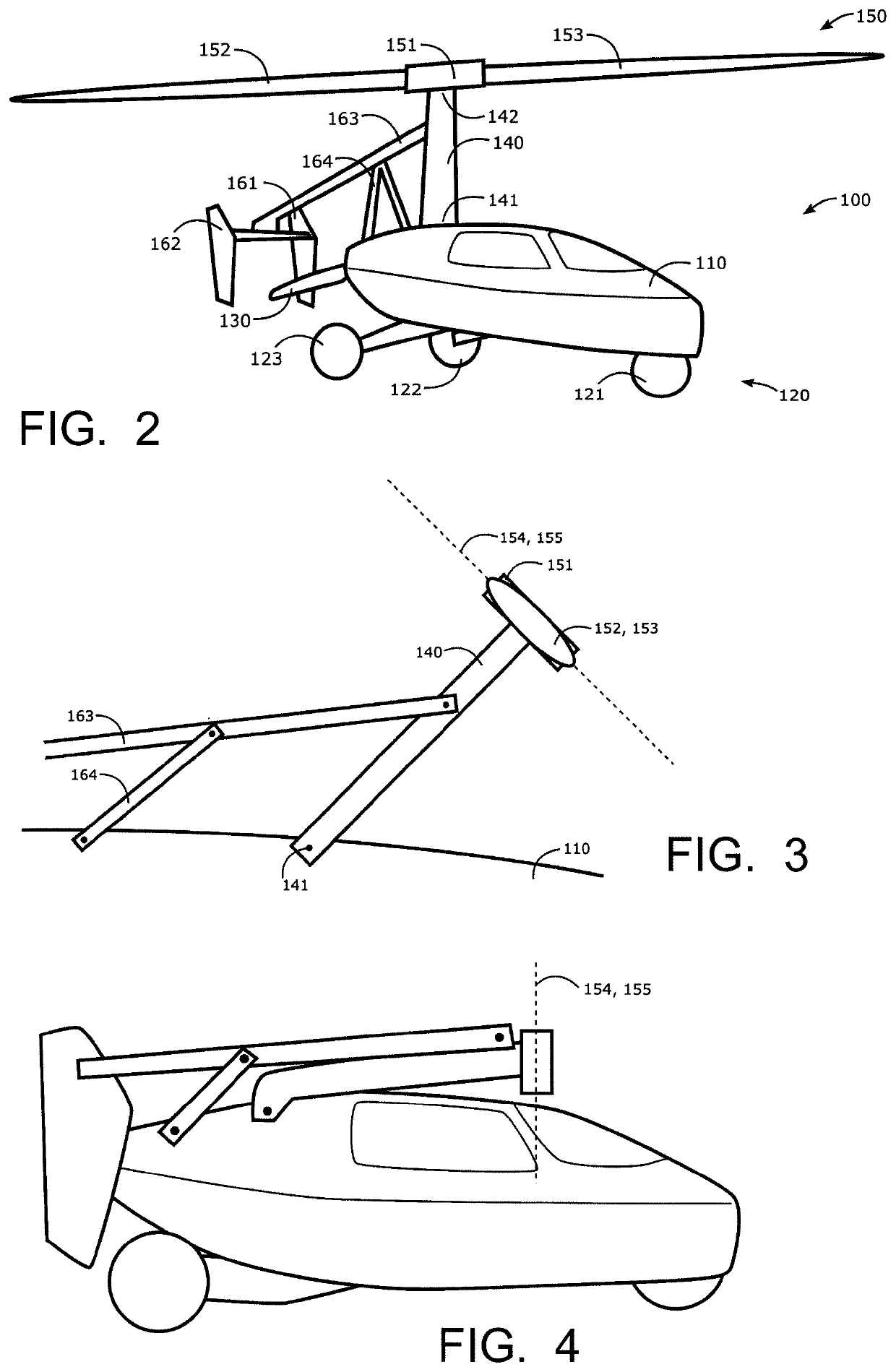
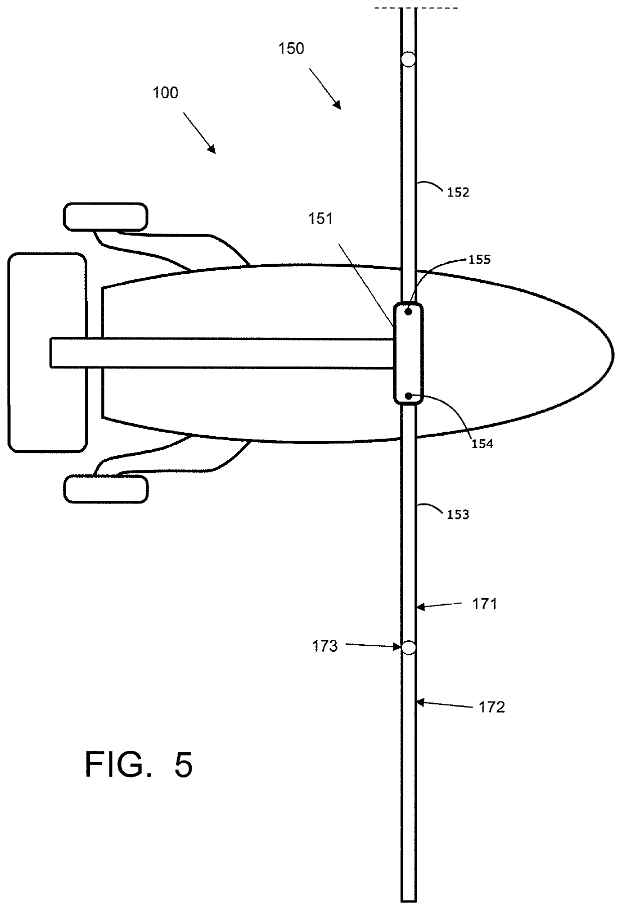
[0034]FIG. 2 is a perspective view of a convertible fly / drive vehicle 100 according to the present invention. The vehicle 100 comprises a slender vehicle body 110, that contains an inner compartment for passengers, and that has a size comparable to the size of a car. The vehicle 100 has an undercarriage 120, comprising a front wheel 121 and two rear wheels 122, 123. At its rear end, the vehicle 100 comprises a propeller 130 for propulsion in fly mode, which propeller can be folded and accommodated within the vehicle body in drive mode.
[0035]The vehicle 100 accommodates an engine (not shown for sake of simplicity). In drive mode, the engine power is transferred to the rear wheels for propelling the vehicle as a normal car on a road. In fly mode, the engine power is transferred to the propeller 130 for providing propulsion in air.
[0036]The vehicle 100 has a mast 140, having its lower end 141 hinged to the top of the vehicle body 110, at a position close to the rear end of the vehicle ...
PUM
 Abstract
Description
Claims
Application Information