Correction of magnetic resonance images using simulated magnetic resonance images

a magnetic resonance image and correction technology, applied in the field of magnetic resonance imaging, can solve the problems of various distortions or artifacts present in the reconstructed image, and achieve the effect of relatively quick calculation

Active Publication Date: 2022-06-09
KONINKLJIJKE PHILIPS NV
View PDF3 Cites 0 Cited by
  • Summary
  • Abstract
  • Description
  • Claims
  • Application Information

AI Technical Summary

Benefits of technology

[0024]This embodiment may be beneficial because the B0 map, the T1 map, the T2 map, and a magnetization map may all be calculated relatively quickly using magnetic resonance fin

Problems solved by technology

However, depending upon the particular imaging protocol there may b

Method used


Image

  • Correction of magnetic resonance images using simulated magnetic resonance images
  • Correction of magnetic resonance images using simulated magnetic resonance images
  • Correction of magnetic resonance images using simulated magnetic resonance images

Examples


Embodiment Construction

[0057]Like numbered elements in these figures are either equivalent elements or perform the same function. Elements which have been discussed previously will not necessarily be discussed in later figures if the function is equivalent.

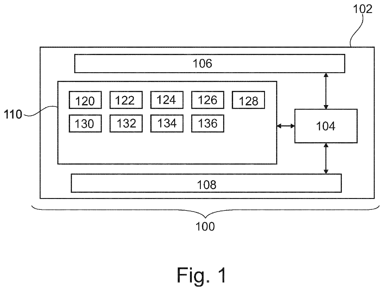
[0058]FIG. 1 illustrates of an example of a medical imaging system 100. The medical imaging system 100 depicted in FIG. 1 comprises a computer 102. The computer comprises a processor 104. The processor 104 is intended to represent one or more processors or processing cores. The processors 104 may also be distributed amongst multiple computer systems 102. There is a hardware interface 106 which is connected to the processor 104. The hardware interface 106 may for example be used for forming a network connection with other computer systems, controlling other components of the medical imaging system 100, or interfacing with other equipment. There is also a user interface 108 which is also connected to the processor 104. There is a memory 110 connected to t...


PUM


Abstract

Disclosed is a medical imaging system (100, 300). The execution of machine executable instructions (120) causes a processor (104) to: receive (200) measured magnetic resonance imaging data (122) descriptive of a first region of interest (307) of a subject (318); receive (202) a B0 map (124), a T1 map (126), a T2 map (128), and a magnetization map (130) each descriptive of a second region of interest (309) of the subject; receive (204) pulse sequence commands (132); calculate (206) a simulated magnetic resonance image (136) of an overlapping region of interest (311) using at least the B0 map, the T1 map, the T2 map, the magnetization map, and the pulse sequence commands as input to a Bloch equation model (134); and reconstruct (208) a corrected magnetic resonance image from the measured magnetic resonance imaging data for the overlapping region of interest by solving an inverse problem. The inverse problem comprises an optimization of a cost function and a regularization term formed from the simulated magnetic resonance image.

Description

FIELD OF THE INVENTION[0001]The invention relates to magnetic resonance imaging, in particular to image reconstruction for magnetic resonance imaging.BACKGROUND OF THE INVENTION[0002]A large static magnetic field is used by Magnetic Resonance Imaging (Mill) scanners to align the nuclear spins of atoms as part of the procedure for producing images within the body of a patient. This large static magnetic field is referred to as the B0 field or the main magnetic field. By applying time dependent magnetic field gradients and radio frequency (RF) pulses various quantities or properties of the subject can be measured spatially using MM. However, depending upon the particular imaging protocol there may be various distortions or artifacts present in a reconstructed image.[0003]United States Patent application publication US20050270024A1 discloses a method of parallel imaging reconstruction in parallel magnetic resonance imaging reconstruction. Magnetic resonance data is acquired in parallel...

Claims


Application Information

Patent Timeline
IPC IPC(8): G01R33/56G06T11/00G01R33/50A61B5/055
CPCG01R33/5608A61B5/055G01R33/50G06T11/006G01R33/565G01R33/5611G01R33/56563G01R33/56554
Inventor VALVANO, GIUSEPPEDE WEERDT, ELWIN
Owner KONINKLJIJKE PHILIPS NV
Why Eureka
Try Eureka