Display device

a display device and display technology, applied in the field of display devices, can solve the problems of reducing contrast and coloring when viewed in an oblique direction, and achieve the effect of suppressing reflection

Pending Publication Date: 2022-06-09
SHARP KK
View PDF0 Cites 0 Cited by
  • Summary
  • Abstract
  • Description
  • Claims
  • Application Information

AI Technical Summary

Benefits of technology

[0008]According to one aspect of the disclosure, by absorbing light in the semi-transparent metal layer, reflectivity can be suppressed; therefore, a known circular polarizer used to suppress the reflectivity is not required. Consequently, according to an aspect of the disclosure, a display device capable of suppressing external light reflection without using a circular polarizer can be provided.

Problems solved by technology

Accordingly, such a display device has high external light reflectivity, and has problems such that when used at a location near a window or outdoors, the light emitted directly from the light-emitting layer interferes with the light reflected inside the display device and then emitted therefrom, which results in reduction in contrast and occurrence of coloring when viewed in an oblique direction.

Method used


Image

  • Display device
  • Display device
  • Display device

Examples


first embodiment

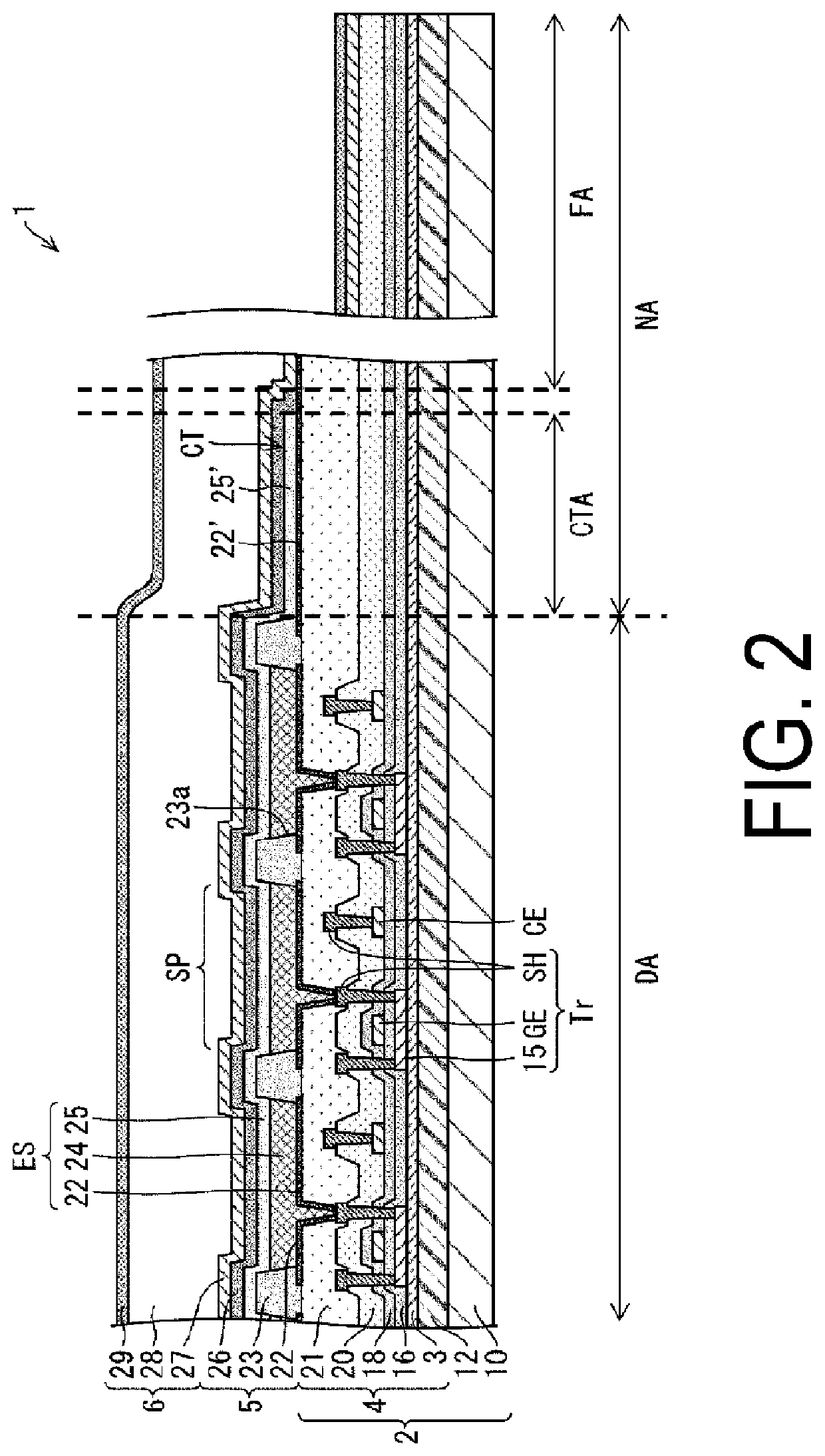
[0019]FIG. 2 is a cross-sectional view illustrating a schematic configuration of a main portion of a display device 1 according to the present embodiment.

[0020]As illustrated in FIG. 2, the display device 1 according to the present embodiment is a self-luminous display device including a configuration in which a light-emitting element layer 5 is disposed on a support body 2. The light-emitting element layer 5 is covered by a sealing layer 6. Hereinafter, the sealing layer 6 side will be referred to as the upper side (upper layer side), and the support body 2 side will be referred to as the lower side (lower layer side).

[0021]Note that in the present embodiment, a case is described as an example in which the support body 2 is an active matrix substrate including a configuration described below. However, as long as the support body 2 is an array substrate provided with an active element such as a thin film transistor (TFT), the support body 2 is not particularly limited.

[0022]The supp...

second embodiment

[0119]Differences from the first embodiment will be described in the present embodiment. Note that, for convenience of description, members having the same function as the members described in the first embodiment are designated by the same reference numbers, and descriptions thereof are omitted.

[0120]FIG. 10 is a cross-sectional view illustrating a schematic configuration of each of the light-emitting elements ESR, ESG, ESB in the light-emitting element layer 5 of the display device 1 according to the present embodiment.

[0121]As illustrated in FIG. 10, the display device 1 according to the present embodiment is the same as the display device 1 according to the first embodiment, except in that the second transparent electrode 34 is disposed between the reflective metal layer 32 and the semi-transparent metal layer 33 in each of the light-emitting elements ESR, ESG, ESB.

[0122]In other words, in the display device 1 according to the present embodiment, the first electrode 22 in each l...

modification example 1

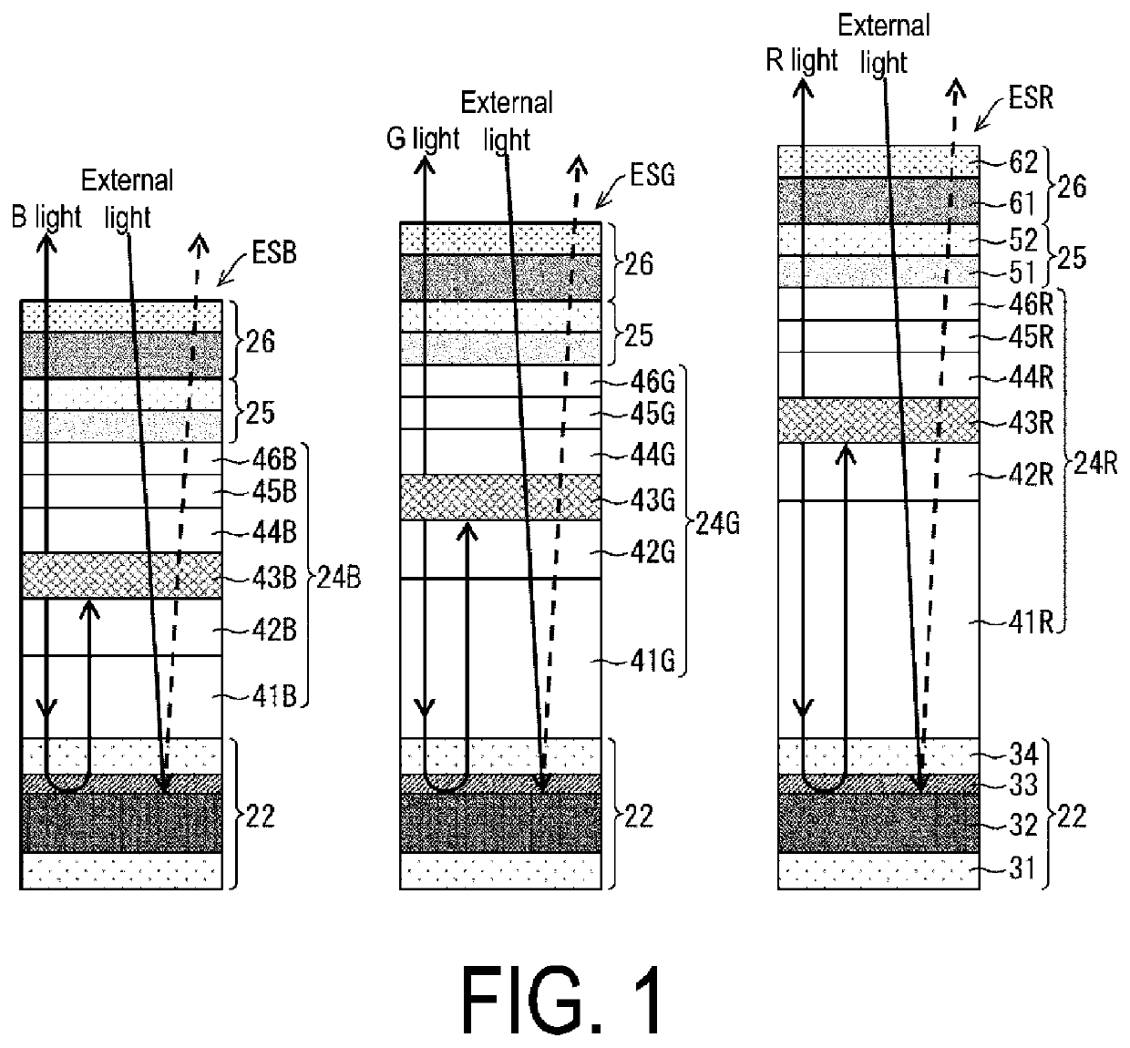
[0124]Further, in the first and second embodiments, a case in which the semi-transparent metal layer 33 of one layer is provided is described as an example, but the present embodiment is not limited thereto. The semi-transparent metal layer 33 of at least one layer is preferably provided between the reflective metal layer 32 and the function layer 24, and although not illustrated, the semi-transparent metal layer 33 may be provided between the reflective metal layer 32 and the second transparent electrode 34 as illustrated in FIG. 1 and between the second transparent electrode 34 and the function layer 24 as illustrated in FIG. 10. In other words, the semi-transparent metal layer 33 may include a first semi-transparent metal layer and a second semi-transparent metal layer, and the first electrode 22 of each light-emitting element ES may include the first transparent electrode 31, the reflective metal layer 32, the first semi-transparent metal layer, the second transparent electrode ...


PUM

PropertyMeasurementUnit
work functionaaaaaaaaaa
thicknessaaaaaaaaaa
thicknessaaaaaaaaaa

Abstract

A display device includes a light-emitting element layer including a plurality of light-emitting elements in each of which a first electrode, a function layer including a light-emitting layer, and a second electrode are disposed in this order from a thin film transistor layer side, and the first electrode includes a first transparent electrode, a reflective metal layer, and a semi-transparent metal layer in this order from the side opposite to the light-emitting layer.

Description

TECHNICAL FIELD[0001]The disclosure relates to a display device that can suppress external light reflection without using a circular polarizer.BACKGROUND ART[0002]A display device such as a top-emitting organic EL (electroluminescence) display device includes a metallic reflective layer made of, for example, highly reflective metal such as silver on the lower layer side of a light-emitting layer. Accordingly, such a display device has high external light reflectivity, and has problems such that when used at a location near a window or outdoors, the light emitted directly from the light-emitting layer interferes with the light reflected inside the display device and then emitted therefrom, which results in reduction in contrast and occurrence of coloring when viewed in an oblique direction.[0003]Therefore, in a display device such as a known organic EL display device, in order to suppress external light reflection, a circular polarizer is generally adhered to a display surface. For e...

Claims


Application Information

Patent Timeline
Patent Type & Authority Applications(United States)
IPC IPC(8): H01L51/52H01L27/32
CPCH01L51/5284H01L51/5218H01L27/3248H01L2251/558H01L51/5234H01L27/3211H05B33/26H05B33/28G09F9/30H10K50/816H10K50/818H10K50/858H10K50/86H10K50/865H10K59/35H10K50/828H10K59/123H10K2102/351
Inventor NIBOSHI, MANABU
Owner SHARP KK
Why Eureka
Try Eureka