[0010]A thin film composed of the above described silver
alloy shows a certain effect of having improved
corrosion resistance. Then, a problem of the corrosion should have been solved, but an optical recording medium using a thin film formed from the silver
alloy still can not completely inhibit a recording error caused by the degradation of the reflection film. On the other hand, a material more excellent in reflectance-keeping characteristics than ever has been required along with requirement to a further improvement of a recording speed and
recording density toward future.
[0014]Then, the present inventors studied a technique for inhibiting silver atoms from migrating in a thin film; examined silver alloys having the effect; found that it is effective as a further improved remedy for inhibiting the silver atoms from migrating to disperse a silver compound phase in silver or a silver alloy, and thus formed thin film acquires superior reflectance-keeping characteristics; and arrived at the present invention.
[0016]In the present invention, by dispersing the phase consisting of the above described three compounds in a matrix formed of silver or a silver alloy, it becomes possible to inhibit the migration of silver atoms composing the matrix, to maintain the flatness of a thin film, and thereby to inhibit the reflectance from lowering even when the thin film has received heat.
[0026]A first technique is a method of using a target having a structure and a composition similar to a thin film to be produced, specifically, is a method of using a
sputtering target prepared by dispersing a compound phase comprising at least one of
nitride,
oxide,
complex oxide, nitroxide,
carbide,
sulfide,
chloride,
silicide,
fluoride,
boride,
hydride,
phosphide,
selenide and
telluride of
gallium,
palladium or
copper, in a matrix formed of silver or a silver alloy. The method can produce the thin film with the use of one sheet of target, accordingly can produce the thin film by a
sputtering technique with a form of arranging the target so as to face a substrate, which is ordinarily employed when producing a reflection film, and consequently produce the thin film with adequate productivity. Here, there are further three forms in the
sputtering target for producing the thin film according to the present invention, as will be described below.
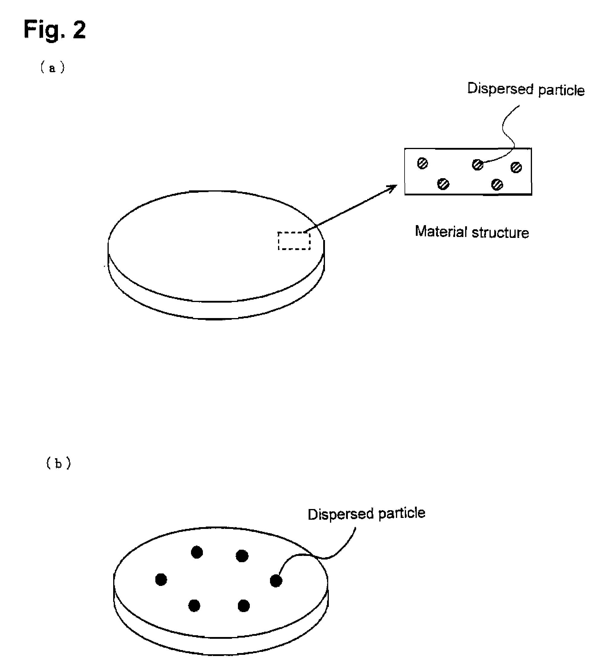
[0029]A third form is an embedded type target. The embedded type target is prepared by preparing a target made from pure silver or a silver alloy, and embedding a small piece (with a cylindrical shape and a spherical shape though the shape is not limited) containing a compound which is to be dispersed, into a region to be consumed by the sputtering. The above described internally chemically-combined type target and sintered target have a composition and a structure microscopically close to those of a thin film to be produced, as is shown in FIG. 2(a), whereas this target has those macroscopically close to the thin film to be produced, as is shown in FIG. 2(b). When the target is used, the composition of the thin film to be produced can be controlled by changing a
diameter of the small piece of the compound to be embedded, positions of the small pieces to be arranged, the number of the pieces and a sputtering rate.
[0035]The reactive sputtering technique may be singularly used, but may be used in combination with another technique. For instance, when using the above described special integral target, specifically, using an internally chemically-combined target, a sintered target and an embedded type target, and when it is anticipated that a content of a compound in a thin film will be insufficient only by singly using the targets, it is possible to increase the content of a compound in the thin film by introducing a
reactive gas into an
atmosphere in a sputtering apparatus. In addition, when producing a thin film by using a co-sputtering technique as well, it is possible to adjust the amount of the compound by using the reactive sputtering technique in combination with the co-sputtering technique.

