
Microplate for microscopy

a micro-scopy and micro-scopy technology, applied in the field of micro-scopy, can solve the problems of death of cells, vertical illumination, and thus excitation, and it is difficult to monitor them using a regular optical microscop

Pending Publication Date: 2022-06-16
PHASE HOLOGRAPHIC IMAGING PHI
View PDF0 Cites 0 Cited by
  • Summary
  • Abstract
  • Description
  • Claims
  • Application Information

AI Technical Summary

Benefits of technology

The patent describes a microplate that can hold and cultivate cells, allowing for fluorescent microscopy and regular vertical illumination microscopy. The microplate has a special design that can facilitate the reflection of light beams directed towards the cells. This design also allows for easy access to the cell culture environment, providing nutrition to the cells. Overall, the microplate provides a convenient and efficient platform for studying cells in a 3D environment.

Problems solved by technology

Since most cells are transparent it may be difficult to monitor them using a regular optical microscope.
However, such colorings often result in the death of the cells which prevents phenomena of living cells from being observed.
A problem with conventional microplates is that they only allow vertical illumination, and thus excitation, of the fluorescent molecules.
It is not possible to illuminate, and thus excite the fluorescent molecules of, portions of the cells which extend in a horizontal direction, that is a direction which is perpendicular to the imaging axis.

Method used


Image

  • Microplate for microscopy
  • Microplate for microscopy

Examples


Embodiment Construction

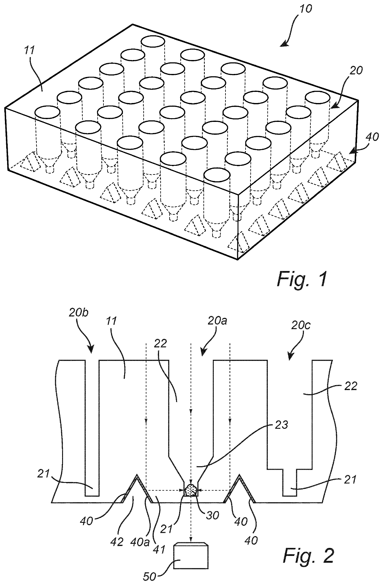
[0075]In FIG. 1 a microplate 10 can be seen. The microplate 10 is for microscopy of an organoid 30.

[0076]The microplate 10 has the shape of a cuboid. Other shapes are also possible, for example a cylindrical shape.

[0077]The microplate comprises a body 11. The body 11 has a plurality of recesses 20 in the form of wells 20. The body 11 may have just one recess 20 or a plurality of recesses 20.

[0078]The body 11 is made of a transparent material. The material at least being transparent to the light being used for microscopy. The body 11 may be made of transparent polystyrene.

[0079]The recesses 11 extend from a top side of the microplate 10 towards a bottom side of the microplate 10. The recesses 11 are open on the top side of the microplate 10, but do not extend through the entire height of the microplate 10.

[0080]In FIG. 1 the recesses 20 are arranged in a matrix on the microplate 10. Other arrangements are also possible, ordered or non-ordered.

[0081]The recesses 11 are each adapted to...


PUM

PropertyMeasurementUnit
widthaaaaaaaaaa
widthaaaaaaaaaa
widthaaaaaaaaaa

Abstract

The invention relates to a microplate (10) for microscopy of an organoid (30), comprising: a body (11) having at least one recess (20), the recess (20) being adapted to contain and restrict movement of the organoid (30), and a reflective surface (40), the reflective surface (40) being inclined in relation to the recess (20), such that an incoming beam of light towards the microplate (10) is directed onto the organoid (30) in a substantially horizontal direction.

Description

FIELD OF THE INVENTION[0001]The invention relates to a microplate for microscopy of an organoid and to a method for microscopy of an organoid.BACKGROUND OF THE INVENTION[0002]A common container for growing cells, such as in an organoid, is called a microplate. Microplates are flat plates, most often made of plastic, which have a plurality of wells arranged in a matrix on them. Each well may typically hold between several nanoliters and several milliliters of liquid and are used as small test tubes in which cells may be cultured. Typical microplates may have anywhere between 6 and 1536 wells arranged in a rectangular matrix. The wells are typically formed as cylinders in the microplate having an open top and a closed bottom such that they may hold a small amount of liquid.[0003]When growing cells in a well of a microplate it is desirable to be able to monitor the cells, for instance to monitor the cell growth or the current number of cells. The microplate may thus be placed in a micr...

Claims


Application Information

Patent Timeline
Patent Type & Authority Applications(United States)
IPC IPC(8): B01L3/00G01N21/64G01N21/03G06T7/00
CPCB01L3/5085G01N21/6452G01N21/6458G01N21/03G06T7/0012G06T2207/30024B01L2300/0829G01N2021/0367G06T2207/10056G06T2207/10064B01L2300/168B01L2300/0654C12M41/36
Inventor EGELBERG, PETERBERGKVIST, JONAS
Owner PHASE HOLOGRAPHIC IMAGING PHI
Learn More