Discharge lamp unit with heat dissipation structure

a technology of discharge lamp and heat dissipation structure, which is applied in the direction of point-like light source, lighting and heating apparatus, lighting support devices, etc., can solve the problem of not being able to easily heat the circuit board, and achieve the effect of not being able to hea

Inactive Publication Date: 2013-06-04
DENSO CORP
View PDF10 Cites 0 Cited by
  • Summary
  • Abstract
  • Description
  • Claims
  • Application Information

AI Technical Summary

Benefits of technology

[0009]In a discharge lamp unit such as this, the thermal absorption protect section inhibits absorption of radiant heat from the discharge lamp by the casing member. Therefore, the amount of heat generated by the discharge lamp reaching the circuit board may be reduced. As a result, the circuit board is not easily heated.
[0010]As a specific configuration of the thermal absorption protect section, for example, the thermal absorption protect section is merely required to be configured in a layered state such that at least a portion of the surface of the casing member on the side on which the supporting member is exposed is covered. The thermal absorption protect section may be configured as a reflective layer that facilitates reflection of radiant heat from the discharge lamp or a heat-insulating layer that prevents heat absorbed by the surface of the casing material from being transferred within the casing member.
[0011]In the discharge lamp unit described in the present invention, a heat-radiation section that facilitates radiation of heat in the casing member to the outside of the casing member is formed on at least a portion of a surface of the casing member excluding the surface on the side on which the supporting member is exposed.
[0012]In a discharge lamp unit such as this, because the heat-radiation section is provided, the heat in the casing member is more easily radiated to the outside of the casing member. As a configuration of the heat-radiation section, for example, the heat-radiation section may be a heat-radiating layer configured such that material surface thermal emissivity, and thermal conductivity between air and the heat-radiating layer are higher than those of the casing material. Alternatively, the heat-radiation section may be a heat-radiating member having a plurality of projections and recesses, or projecting sections to increase a surface area of the casing member.

Problems solved by technology

As a result, the circuit board is not easily heated.

Method used


Image

  • Discharge lamp unit with heat dissipation structure
  • Discharge lamp unit with heat dissipation structure
  • Discharge lamp unit with heat dissipation structure

Examples


Embodiment Construction

[0022]Preferred embodiments of the present invention will hereinafter be described with reference to the drawings.

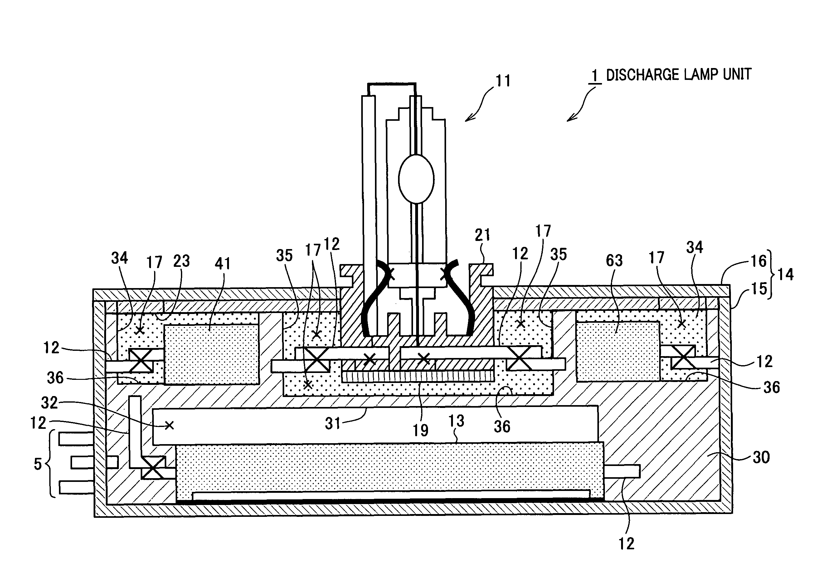
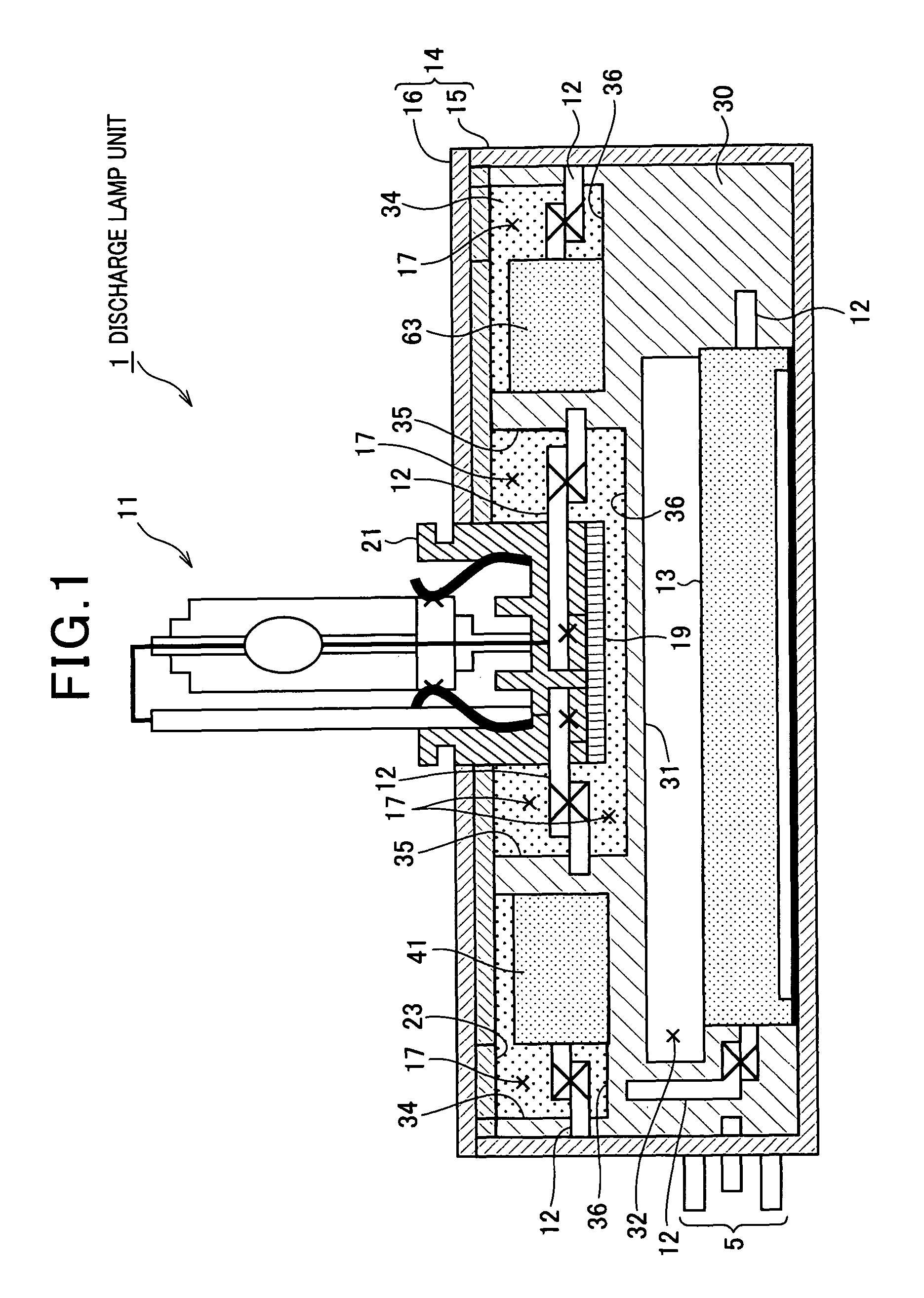
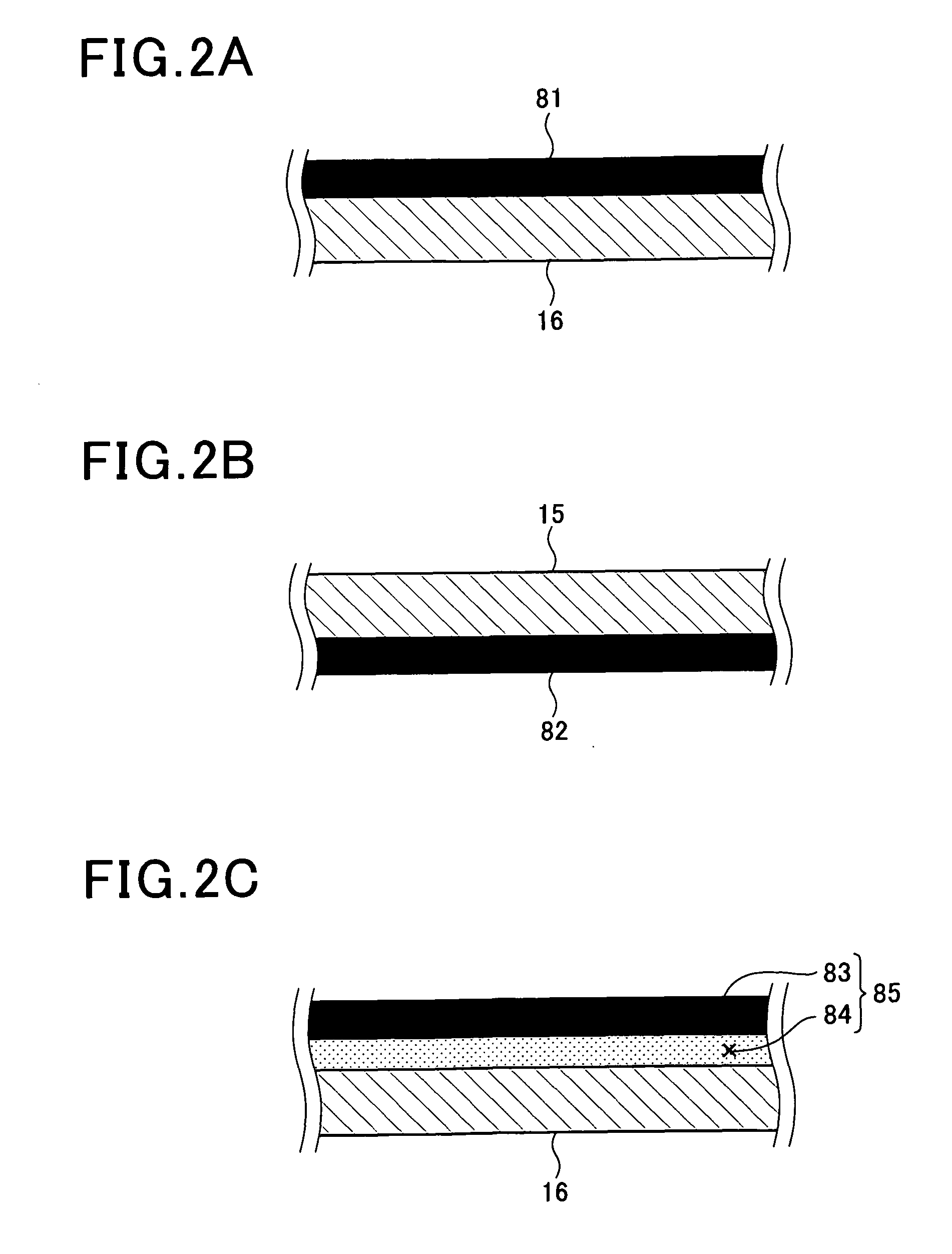
[0023]FIG. 1 is a center cross-sectional view of a discharge lamp unit 1 to which the present invention is applied. FIG. 2 is an enlarged cross-sectional view of a casing member 14.

[0024]As shown in FIG. 1, the discharge lamp unit 1 is configured such that each constituent element for supplying power to light a discharge lamp 11 is housed within the casing member 14. More specifically, the casing member 14 is made of, for example, aluminum. The casing member 14 houses therein a circuit board 13 including an integrated circuit, such as an integrated circuit (IC) chip, circuit components, such as a coil and a capacitor, wirings 12 that electrically connect the circuit board 13 and the circuit components, and the like. The casing member 14 holds a discharge lamp supporting section 21 (supporting member) for supporting the discharge lamp 11 in a state in which the discharge ...


PUM


Abstract

In a discharge lamp unit, a casing member arranged such that the casing member holds a circuit board therein and holds a discharge lamp supporting section being exposed outside of the casing member. A thermal absorption protect layer is formed on the surface on the side on which the discharge lamp supporting section is exposed. The thermal absorption protect layer allows the casing member to inhibit absorption of radiant heat induced by the discharge lamp. Since the thermal absorption protect layer inhibits the casing member from absorbing the radiant heat from the discharge lamp, the amount of heat generated by the discharge lamp reaching the circuit board may be reduced. Therefore, the circuit board is not easily heated.

Description

CROSS-REFERENCE TO RELATED APPLICATION[0001]This application is related to Japanese Patent Application No. 2009-94047 filed on Apr. 8, 2009, the contents of which are hereby incorporated by reference.BACKGROUND OF THE INVENTION[0002]1. Field of the Invention[0003]The present invention relates to a discharge lamp unit. In particular, the present invention relates to a discharge lamp unit including a supporting member that supports a discharge lamp and a circuit board that supplies power to the discharge lamp.[0004]2. Description of the Related Art[0005]Conventionally, a discharge lamp unit is designed taking into consideration heat conduction within the discharge lamp. For example, in Japanese Patent Laid-open Publication No. 2003-022702, as the above-described discharge lamp unit, a technology is disclosed in which the material used to form a casing that houses a circuit board is changed to a material that does not easily conduct heat to inhibit conduction of heat generated by a dis...

Claims


Application Information

Patent Timeline
Patent Type & Authority Patents(United States)
IPC IPC(8): F21V29/00F21V19/00F21V21/00F21Y101/00
CPCH01J5/54H01J61/52H01J61/56
Inventor YOSHIKAWA, SYOTAWANDA, YOSHIHIRO
Owner DENSO CORP
Why Eureka
Try Eureka