Heat exchange circuit for a geothermal plant

a geothermal plant and heat exchange circuit technology, applied in geothermal energy generation, collectors with underground reservoirs, lighting and heating apparatus, etc., can solve the problems of low use rate of bottom-well heat exchangers, inability to use closed-cell foams, and inability to achieve the useful area of the cross-section

Pending Publication Date: 2022-06-16
TURBODEN
View PDF29 Cites 16 Cited by
  • Summary
  • Abstract
  • Description
  • Claims
  • Application Information

AI Technical Summary

Benefits of technology

[0025]Together with the portion of the inner duct, also the components dedicated to the heat exchange and / or the movement of geothermal and heat transfer fluids and / or the seals between the two fluid paths, will also raise up to the surface.
[0026]The heat exchange circuit for geothermal plants according to the present invention, shows the characteristics of the independent claim 1 of the plant.
[0027]Further preferred and / or particularly advantageous embodiments of the invention are described according to the characteristics set out in the appended dependent claims.

Problems solved by technology

However, the bottom-well heat exchanger is not commonly used, as it also has several disadvantages.
Due to the high pressure and high temperature, closed-cell foams cannot be used.
In any case, the insulation between two ducts in the same well considerably reduces the useful area of the cross-section and consequently also increases the overall cost of the plant per unit of power produced;any maintenance activity concerning the bottom-well equipment requires to remove the equipment from the bottom, by lifting it to the surface.
By way of example, the replacement of a relatively small device such as an electric pump at 800 m depth requires approximately one month of uninterrupted work.

Method used


Image

  • Heat exchange circuit for a geothermal plant
  • Heat exchange circuit for a geothermal plant
  • Heat exchange circuit for a geothermal plant

Examples


second embodiment

[0083]The present invention is also applicable if a well is already present, for example a vertical well. FIGS. 15 to 18 schematically show this further embodiment of the present invention. In this second embodiment of the invention and with reference to FIG. 15, the pre-existing well 100 is a vertical well on the descending side and comprises a first vertical portion 101 which, starting from the surface of the ground, reaches the level of the aquifer 4, and a second almost horizontal or sub-horizontal portion 102 which extends inside the aquifer itself. This may be, for example, the case of wells almost exhausted wells for the extraction of “shale gas” or gas obtained from artificially fractured clays. According to the invention, it is possible to continue the existing perforation, by creating a further perforation characterized by a small diameter that goes upwards until forming a “slim hole” which exits to the surface at point D (in this and in the following Figures where possibl...

third embodiment

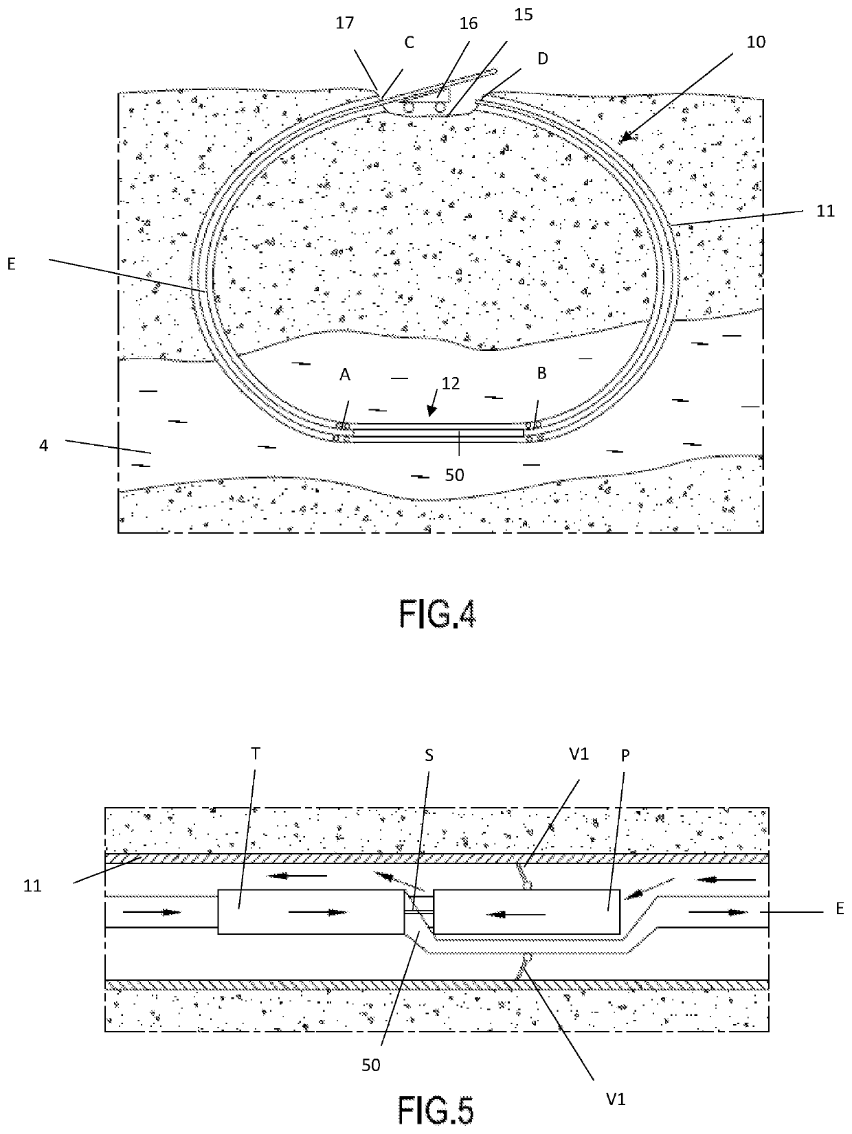
[0099]the invention is shown schematically in FIG. 19. The heat exchange circuit illustrated therein differs from the heat exchange circuit of FIG. 4 for the following characteristics:[0100]the first perforated section extended along the first portion A, the one that acts as a region of re-injection of the less hot geothermal fluid, is configured in such a way that the surface area of the windows is reduced by a desired percentage. At most, this percentage may approach 100%. In this way the geothermal fluid will remain within the desired percentage inside the casing 11, also taking into account the permeability of the rock surrounding the perforated section. At most, in the case of a perforated section A practically equal to zero, the percentage of geothermal fluid remaining within the casing 11 tends to 100% and can be completely transferred to the surface. In an alternative configuration it is also possible to eliminate the presence of the perforated section A;[0101]preferably, a ...


PUM


Abstract

A heat exchange circuit for a geothermal plant comprising a well excavated in the rock, a casing arranged inside the well, integral with it and comprising at least a first perforated section extending along a first portion of the well and at least a second perforated section extending along a second portion of the well, the perforated sections allowing the exit and the entry of a flow of geothermal fluid contained in an aquifer, an internal duct, located inside the casing in which a heat transfer fluid flows, wherein the well, the casing and the internal duct being arranged as a substantially closed ring, except for at least one surface interruption, at least one heat-exchange section at the bottom of the well between the first portion and the second portion of the well within which the geothermal fluid transfers heat to the heat transfer fluid.

Description

CROSS REFERENCE TO RELATED APPLICATIONS[0001]This is a national stage application of PCT application PCT / IB2020 / 053343 having an international filing date of Apr. 8, 2020. This application claims foreign priority based on application Ser. No. 102019000006817 filed with the Italian Patent Office on May 14, 2019.TECHNICAL FIELD OF THE INVENTION[0002]The present invention relates to an innovative heat exchange circuit for a geothermal plant which provides thermal energy to one or more users for the generation of electrical energy and / or for thermal storage.BACKGROUND OF THE INVENTION[0003]It is known that for a geothermal energy, the use of the temperature gradient is meant which is present beneath the earth surface to produce thermal or electric energy, which is one of the most promising ways to provide energy worldwide in the future. In fact, this is a reliable, predictable and in many cases cheap energy source. It is also known that, for heat recovery in geothermal applications, the...

Claims


Application Information

Patent Timeline
Patent Type & Authority Applications(United States)
IPC IPC(8): F24T10/15F24T10/20F24T10/30
CPCF24T10/15F24T2010/53F24T10/30F24T10/20Y02E10/10F24T10/13F03G4/023F03G4/029F03G4/033F03G4/001F03G4/04F03G4/031F03G4/035
Inventor GAIA, MARIOBINI, ROBERTO
Owner TURBODEN
Why Eureka
Try Eureka