Smoking substitute apparatus

Pending Publication Date: 2022-06-30
NERUDIA LTD
View PDF0 Cites 1 Cited by
  • Summary
  • Abstract
  • Description
  • Claims
  • Application Information

AI Technical Summary

Problems solved by technology

The smoking of tobacco is generally considered to expose a smoker to potentially harmful substances.
It is thought that a significant amount of the potentially harmful substances are generated through the burning and/or com

Method used


Image

  • Smoking substitute apparatus
  • Smoking substitute apparatus
  • Smoking substitute apparatus

Examples


examples

[0213]There now follows a disclosure of certain examples of experimental work undertaken to determine the effects of certain conditions in the smoking substitute apparatus on the particle size of the generated aerosol. However, the present disclosure is to be understood to not be limited in its application to the specific experimentation, results, and laboratory procedures disclosed herein after. Rather, the Examples are simply provided as one of various embodiments and are meant to be exemplary, not exhaustive.

Introduction

[0214]Aerosol droplet size is a considered to be an important characteristic for smoking substitution devices. Droplets in the range of 2-5 μm are preferred in order to achieve improved nicotine delivery efficiency and to minimize the hazard of second-hand smoking. However, at the time of writing (September 2019), commercial EVP devices typically deliver aerosols with droplet size averaged around 0.5 μm, and to the knowledge of the inventors not a single commercia...

first example

ube Testing

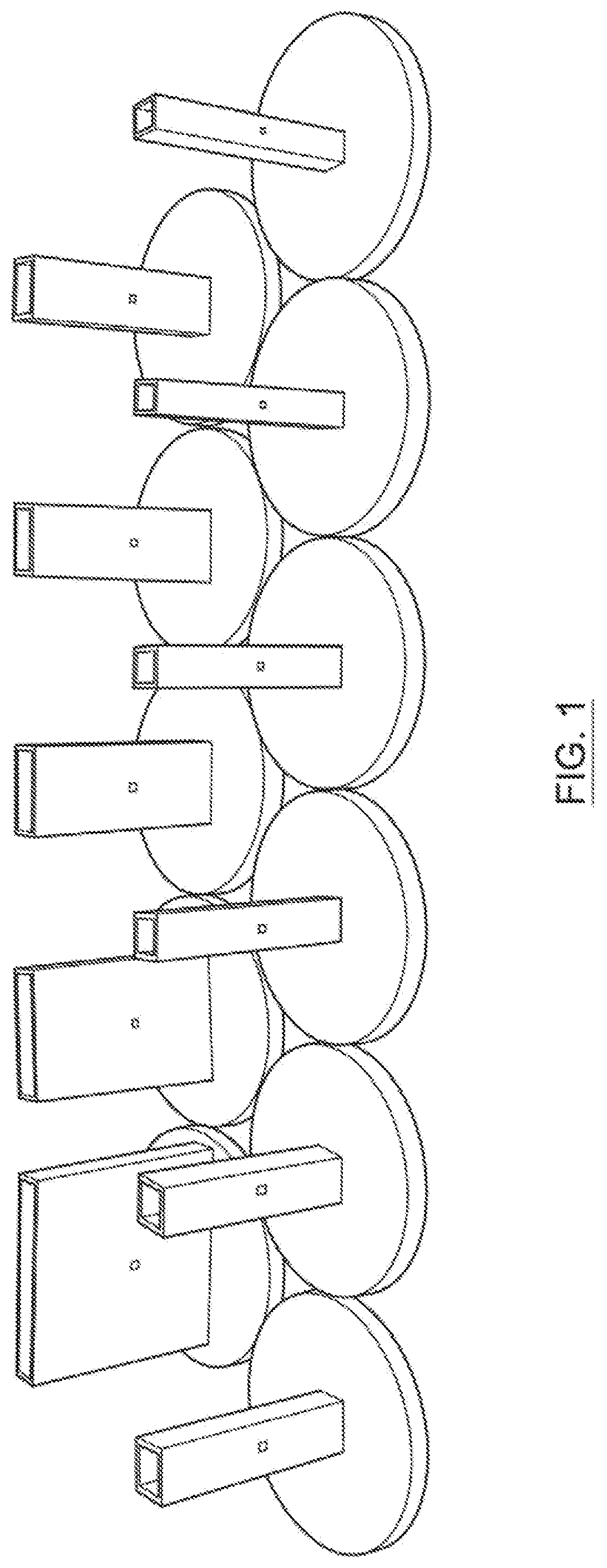
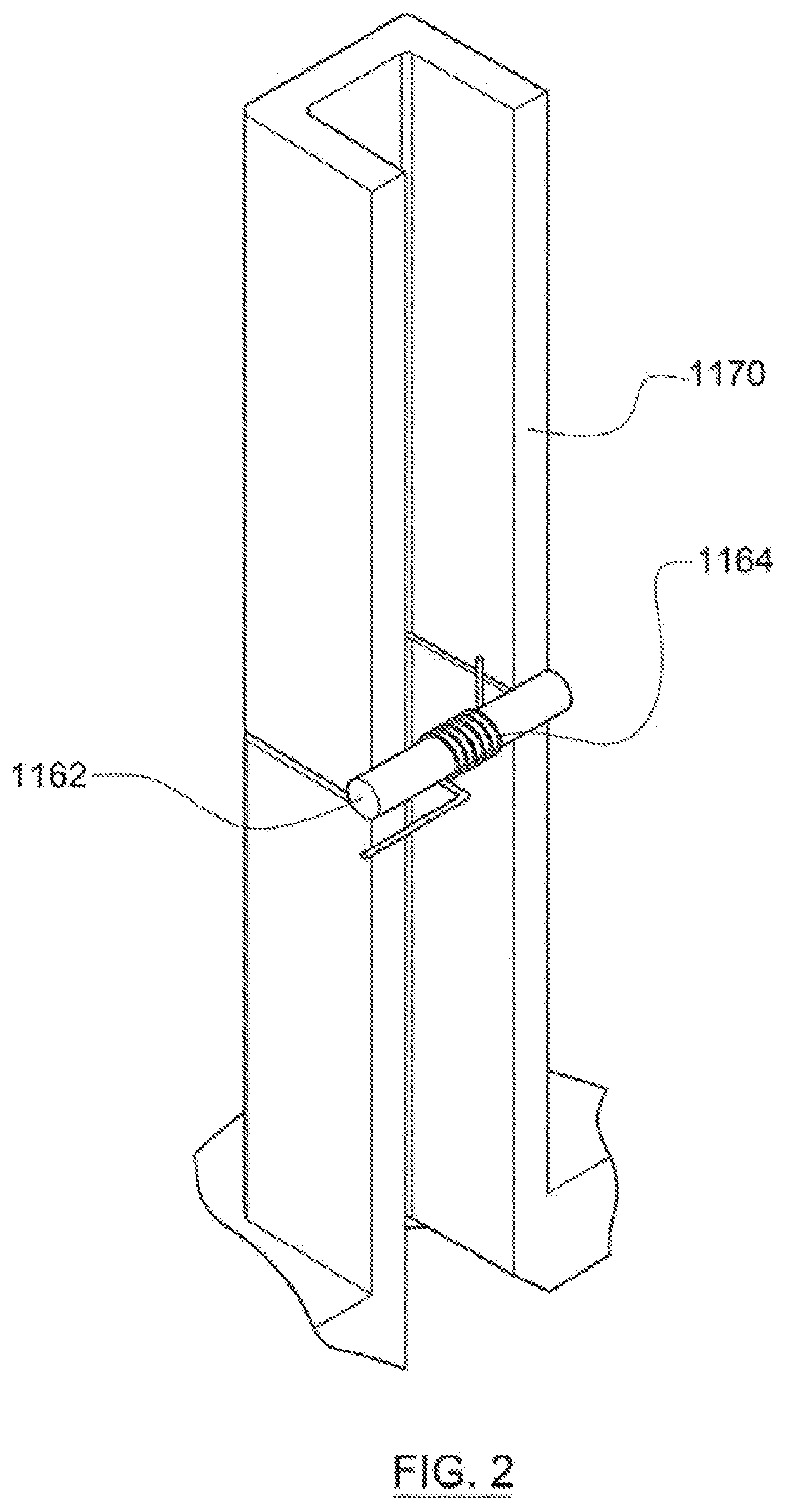
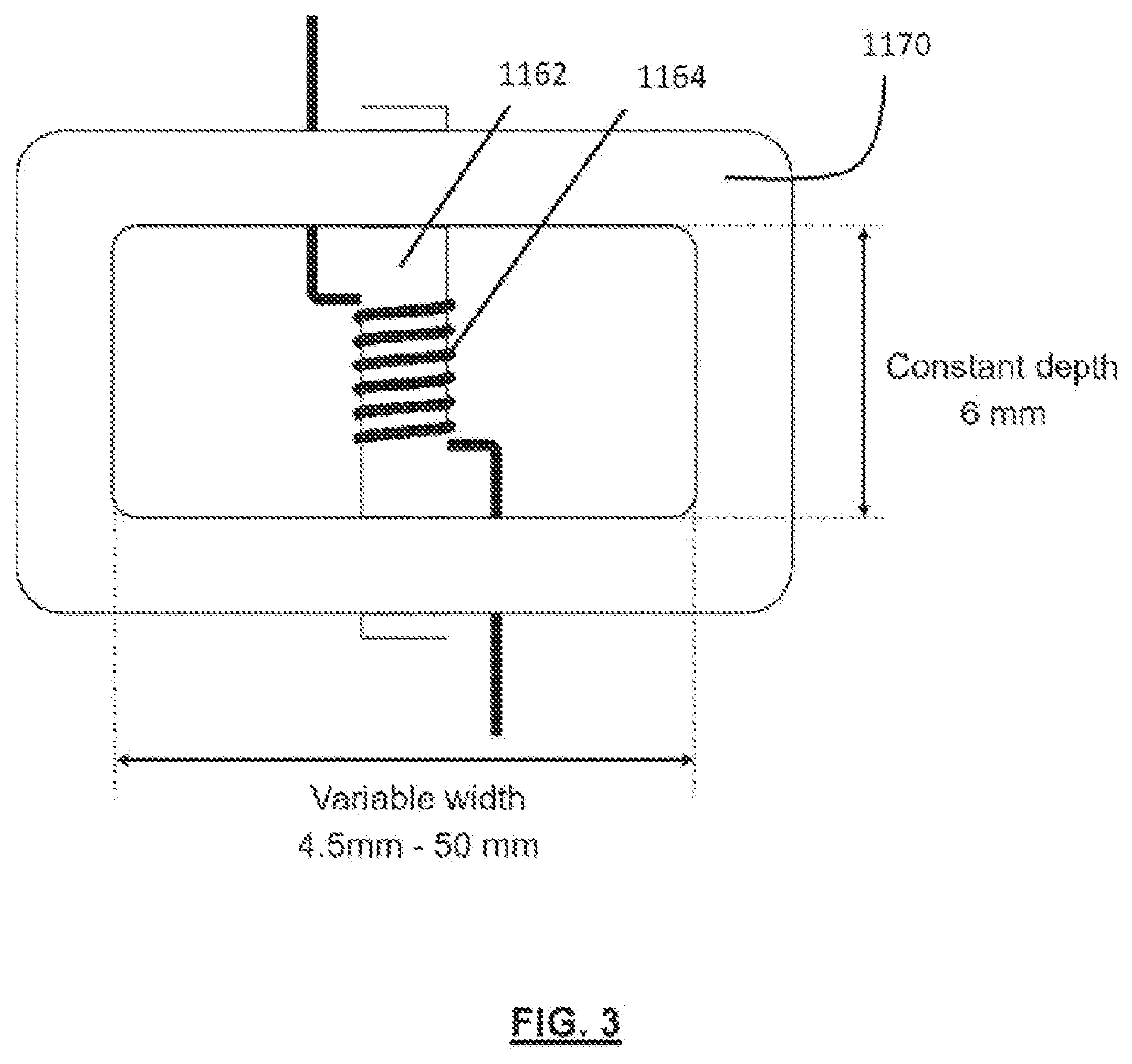
[0220]The work of a first example reported here based on the inventors' insight that aerosol particle size might be related to: 1) air velocity; 2) flow rate; and 3) Reynolds number. In a given EVP device, these three parameters are inter-linked to each other, making it difficult to draw conclusions on the roles of each individual factor. In order to decouple these factors, experiments of a first example were carried out using a set of rectangular tubes having different dimensions. These were manufactured by 3D printing. The rectangular tubes were 3D printed in an MJP 2500 3D printer. FIG. 1 illustrates the set of rectangular tubes. Each tube has the same depth and length but different width. Each tube has an integral end plate in order to provide a seal against air flow outside the tube. Each tube also has holes formed in opposing side walls in order to accommodate a wick.

[0221]FIG. 2 shows a schematic perspective longitudinal cross sectional view of an example rectangul...

fourth example

ling

[0247]Air velocity in the vicinity of the wick is believed to play an important role in affecting particle size. In the first example, the air velocity was calculated by dividing the flow rate by the intersection area, which is referred to as “calculated velocity” in a fourth example. This involves a very crude simplification that assumes velocity distribution to be homogeneous across the intersection area.

[0248]In order to increase reliability of the fourth example, computational fluid dynamics (CFD) modelling was performed to obtain more accurate velocity values:[0249]1) The average velocity in the vicinity of the wick (defined as a volume from the wick surface to 1 mm away from the wick surface)[0250]2) The maximum velocity in the vicinity of the wick (defined as a volume from the wick surface to 1 mm away from the wick surface)

TABLE 2Average and maximum velocity in the vicinity of wick surface obtained from CFD modelling.Tube Flow CalculatedAverageMaximumsizeratevelocity*vel...


PUM


Abstract

A smoking substitute apparatus is disclosed, having: an air inlet; an outlet; and a flow passage formed therebetween. A vaporization chamber is in communication with the flow passage and has an aerosol generator configured to generate an aerosol from an aerosol precursor by heating. The aerosol generator comprises a vaporizer element loaded with aerosol precursor, the vaporizer element being heatable by a heater and presenting a vaporizer element surface to air in the vaporization chamber. A vaporizer element region is defined as a volume extending outwardly from the vaporizer element surface to a distance of 1 mm from the vaporizer element surface. The air inlet, flow passage, outlet and the vaporization chamber are configured so that, when the air flow rate inhaled by the user through the apparatus is 1.3 L min−1, the maximum magnitude of velocity of air in the vaporizer element region is in the range 0-2.0 ms−1.

Description

CROSS-REFERENCE TO RELATED APPLICATIONS / INCORPORATION BY REFERENCE STATEMENT[0001]This application is a non-provisional application claiming benefit to the international application no. PCT / EP2020 / 076311 filed on Sep. 21, 2020, which claims priority to EP 19198722.1 filed on Sep. 20, 2019 and EP 19198560.5 filed on Sep. 20, 2019. The entire contents of each of the above-referenced applications are hereby incorporated herein by reference in their entirety.FIELD OF THE DISCLOSURE[0002]The present disclosure relates to a smoking substitute apparatus and, in particular, a smoking substitute apparatus that is able to deliver nicotine to a user in an effective manner.BACKGROUND[0003]The smoking of tobacco is generally considered to expose a smoker to potentially harmful substances. It is thought that a significant amount of the potentially harmful substances are generated through the burning and / or combustion of the tobacco and the constituents of the burnt tobacco in the tobacco smoke it...

Claims


Application Information

Patent Timeline
IPC IPC(8): A24F40/48A24F40/10A24F40/44A24B15/167
CPCA24F40/48A24B15/167A24F40/44A24F40/10A24F40/485A24F40/46
Inventor ILLIDGE, BENJAMINASTBURY, BENJAMINAGGARWAL, NIKHILLU, HUANGHAIMCKEON, JOHN
Owner NERUDIA LTD
Why Eureka
Try Eureka