Connector fixing structure

Pending Publication Date: 2022-06-30
TOYOTA JIDOSHA KK
View PDF4 Cites 0 Cited by
  • Summary
  • Abstract
  • Description
  • Claims
  • Application Information

AI Technical Summary

Benefits of technology

The present patent provides a connector fixing structure that is easy to assemble and prevents foreign matter from entering the attachment hole. This structure is designed to improve the overall functionality and reliability of the connection.

Problems solved by technology

Therefore, there are cases where the connector cannot easily be assembled to the device case.
In addition, because of the lower side of the shell being not fitted on the wall portion, a gap can be formed between the lower side of the shell and the wall portion.

Method used


Image

  • Connector fixing structure
  • Connector fixing structure
  • Connector fixing structure

Examples


Embodiment Construction

[0034]An embodiment of the present disclosure will be described in detail below with reference to the drawings. In the below-described embodiment, parts that are identical or common to each other are provided with the same sign in the drawings and description thereof will not be repeated.

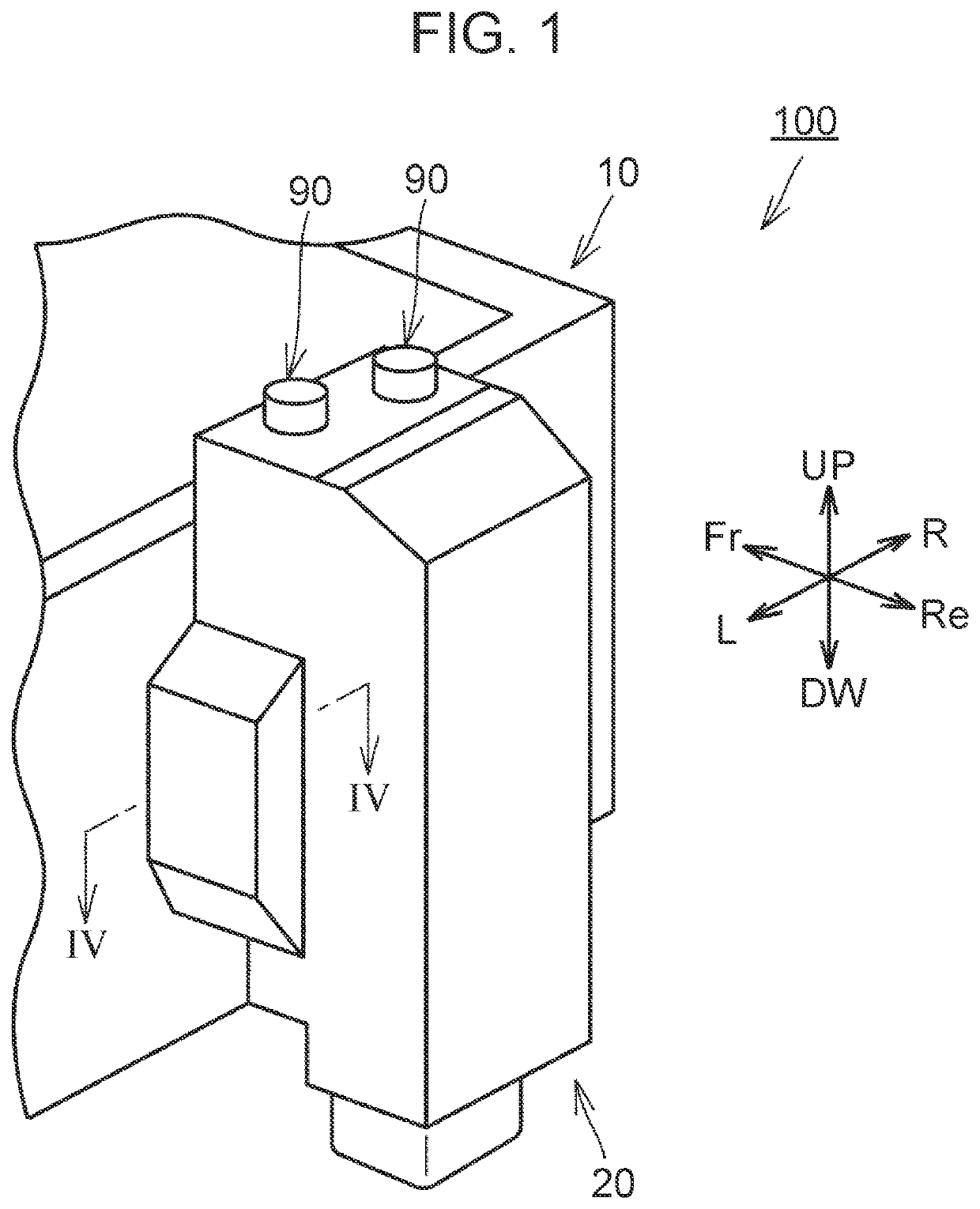
[0035]FIG. 1 is a perspective view illustrating a connector fixing structure according to the embodiment in an assembled state in which a connector is assembled to a device case. A connector fixing structure 100 according to the embodiment will be described with reference to FIG. 1.

[0036]As illustrated in FIG. 1, the connector fixing structure 100 according to the embodiment includes a device case 10 and a connector 20. The device case 10 is disposed on the front side of a vehicle relative to the connector 20. The connector 20 is fixed to the device case 10 via, e.g., fastening members 90.

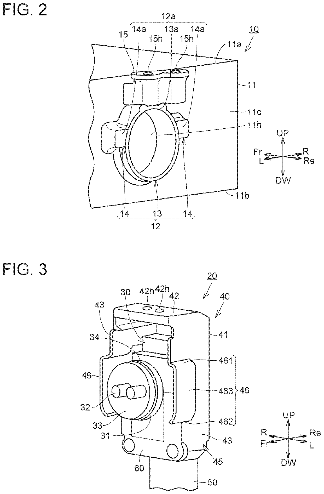
[0037]FIG. 2 is a perspective view of the device case according to the embodiment. The device case 10 will be de...


PUM


Abstract

A connector fixing structure includes: a device case including a wall portion in which an attachment hole is provided; and a connector including a housing fixed to the device case, the housing including an insertion portion inserted in the attachment hole, and a shell covering the housing from the outer side. At a part of the wall portion, the part being located around the attachment hole, a projection portion that projects toward one side in an axis direction of the attachment hole from the wall portion is provided. The projection portion includes a lateral portion on one end side in a lateral direction orthogonal to the axis direction. The shell includes a lateral cover portion that covers the lateral portion.

Description

CROSS-REFERENCE TO RELATED APPLICATION[0001]This application claims priority to Japanese Patent Application No. 2020-217179 filed on Dec. 25, 2020, incorporated herein by reference in its entirety.BACKGROUND1. Technical Field[0002]The present disclosure relates to a connector fixing structure mounted in a vehicle.2. Description of Related Art[0003]Conventionally, Japanese Unexamined Patent Application Publication No. 2015-82464 (JP 2015-82464 A) discloses a fixing structure in which a connector is fixed to a device case mounted in a vehicle by inserting an insertion portion of the connector to a cylindrical portion provided at the device case. The connector includes a housing including the insertion portion to be inserted to the inside of the cylindrical portion, and a shielding shell covering the housing.SUMMARY[0004]However, the shielding shell described in JP 2015-82464 A includes an upper wall portion that covers the upper side of the cylindrical portion and that is fastened to ...

Claims


Application Information

Patent Timeline
IPC IPC(8): H01R13/434H01R13/436
CPCH01R13/434H01R13/4362H01R13/73H01R13/502H01R13/5202H01R13/6581H01R13/5227H01R13/648H01R2201/26H01R13/74H01R13/6596H01R13/6582
Inventor WARASHINA, TAISUKE
Owner TOYOTA JIDOSHA KK
Why Eureka
Try Eureka