Dose Recording Device
Pending Publication Date: 2022-07-14
SANOFI SA
0 Cites 0 Cited by
AI-Extracted Technical Summary
Problems solved by technology
Despite the advantages provided by these drug delivery devices, there are still some dr...
Method used
[0088]The piston rod has a distal end, which is arranged nearest to the dispensing end of the drug delivery device. The distal end section of the piston rod comprises a bearing member. The bearing member is arranged between the bung and the piston rod. The bearing member is configured to reduce damages that may be caused by friction. The bearing member may be part of the piston rod. The bearing member may be connected to the piston rod. Alternatively, the bearing...
Abstract
A dose recording device (100) for a drug delivery device is disclosed, wherein the drug delivery device comprises a housing, a cartridge holder configured to receive a cartridge for holding a plurality of doses of a drug, and a dose setting member connected to the housing and configured to set the dose of the drug. The dose recording device (100) comprises a device housing (102), an electronic controller (114) disposed within the device housing (102), and at least one identifier member (120) configured to be mounted to the device housing (102). The electronic controller (114) comprises switches (116). The identifier member (120) comprises at least one actuation member (122) configured to actuate at least one of the switches (116) when mounted to the device housing (102). An actuation of the switch (116) is configured to provide additional information on the drug.
Application Domain
Ampoule syringesMedical devices +1
Technology Topic
Drug deliveryBiomedical engineering +5
Image
Examples
- Experimental program(1)
Example
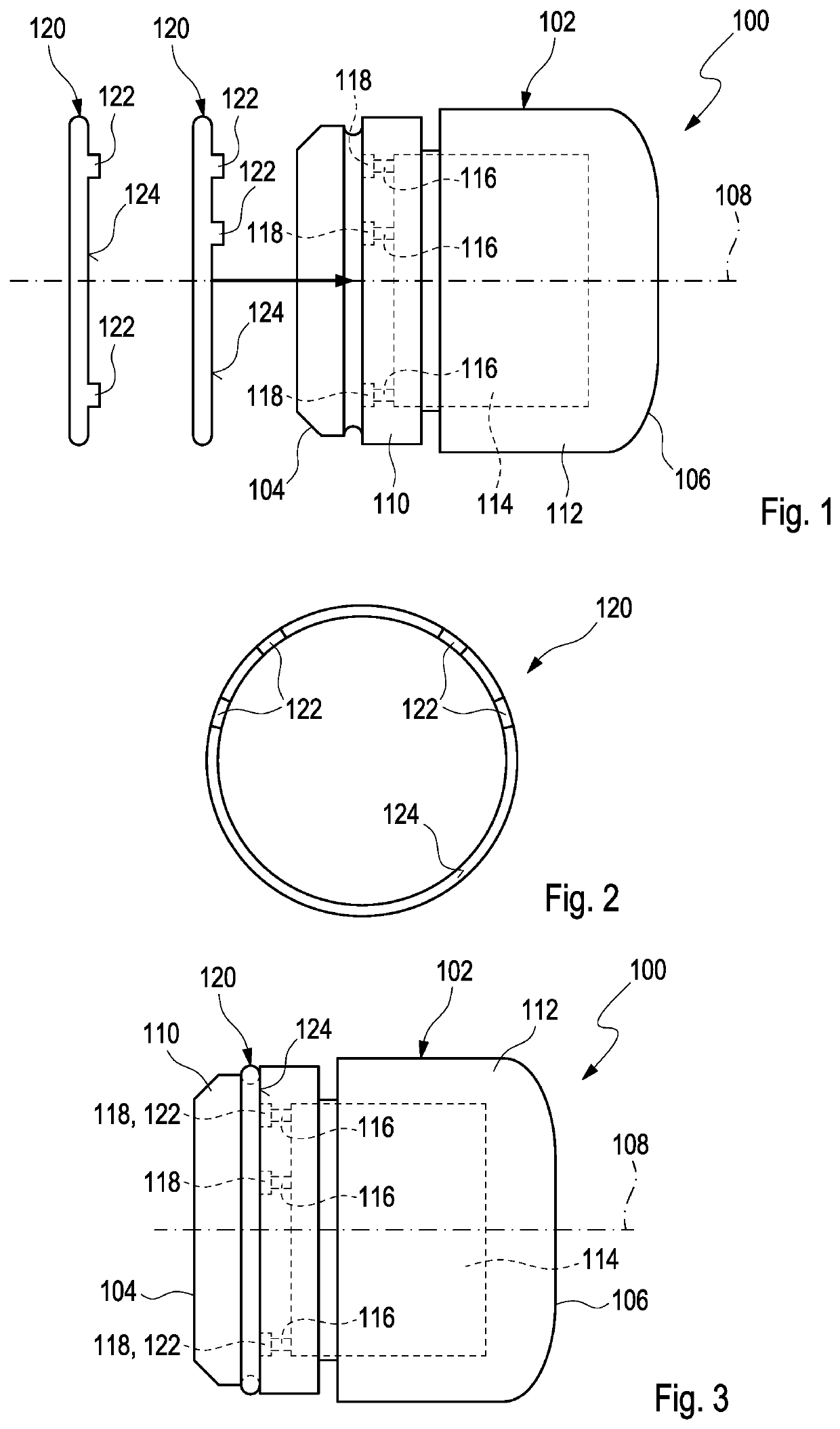
[0084]FIG. 1 shows a side view of a dose recording device 100 according to a first embodiment. The dose recording device 100 is configured to be used with a drug delivery device (not shown). The drug delivery device may be a pen-type device, in particular a pen-type injector such as known from WO 2015/197755 A1, the constructional details of which are incorporated herein by reference. Basically such a drug delivery device comprises a housing. The housing is adapted and arranged for protecting components of the drug delivery device arranged within the housing from environmental influences. The housing has a distal end and a proximal end. The term “distal end” designates that end of the housing which is or is to be arranged closest to a dispensing end of the drug delivery device. The term “proximal end” designates that end of the housing which is or is to be arranged furthest away from the dispensing end of the drug delivery device. The distal end and the proximal end are spaced apart from one another in the direction of an axis. The axis may be the longitudinal axis and/or rotational axis of the drug delivery device. The housing comprises a dose window made of a transparent material.
[0085]The drug delivery device further comprises a cartridge holder. The cartridge holder is configured to receive a cartridge for holding a plurality of doses of a drug. The cartridge contains a drug, preferably a plurality of doses of the drug. The cartridge is retained within the cartridge holder. The cartridge holder stabilizes the position of the cartridge mechanically. The cartridge holder is connectable, e.g. by a threaded engagement or by a bayonet coupling, to the housing at the distal end thereof. The cartridge holder and the housing are releasably connected to one another. Alternatively, the cartridge may be directly connected to the housing. In the latter case, the cartridge holder may be redundant. The drug delivery device may be a re-usable device, which means that the cartridge can be replaced, in particular during a reset operation, by a replacement cartridge for dispensing a plurality of doses from the replacement cartridge.
[0086]A bung (not shown in detail) is slideably retained within the cartridge. The bung seals the cartridge proximally. Movement of the bung in the distal direction with respect to the cartridge causes the drug to be dispensed from the cartridge. A needle assembly (not shown in detail) can be arranged at the distal end section of the cartridge holder, e.g. through an engagement member, e.g. a thread. A cap may be secured to the cartridge holder to protect the drug delivery device and, in particular, the cartridge holder from environmental influences, e.g. when the drug delivery device is not in use.
[0087]The drug delivery device further comprises a dose setting member and a dose button operated for setting and dispensing a dose of the drug. The dose button is located at a proximal end section of the dose setting member. The drug delivery device comprises a piston rod (not shown in detail). The piston rod is configured to transfer movement through the housing for expelling a dose of drug from the cartridge. The piston rod is moveable between an initial position with respect to the housing and an end position with respect to the housing. The initial position may be the position of the piston rod when the drug delivery device is supplied from the manufacturer. Moreover, the initial position may be the position of the piston rod after a reset operation was performed. The initial position may be the most proximal position of the piston rod. The end position may be the position of the piston rod after the complete amount of the drug was dispensed from the cartridge. The end position may be the most distal position of the piston rod. During operation of the drug delivery device, in particular for dispensing a dose of the drug, the piston rod is moved towards the end position.
[0088]The piston rod has a distal end, which is arranged nearest to the dispensing end of the drug delivery device. The distal end section of the piston rod comprises a bearing member. The bearing member is arranged between the bung and the piston rod. The bearing member is configured to reduce damages that may be caused by friction. The bearing member may be part of the piston rod. The bearing member may be connected to the piston rod. Alternatively, the bearing member and the piston rod may be integrally formed. The bearing member and the bung are in mechanical contact, in particular in abutment, throughout the operation of the device. The bearing member and the bung are in mechanical contact as long as the cartridge or a replacement cartridge is loaded within the device. In other words, the bearing member and the bung are in mechanical contact as long as the cartridge holder is at least partly connected to the housing.
[0089]The piston rod is configured as a lead screw. The piston rod comprises two threaded sections. The threaded sections have opposite senses of rotation. A first threaded section is located at a distal part of the piston rod and a threaded section is located at a proximal part of the piston rod. The piston rod and, in particular, the first threaded section, is in threaded engagement with a guiding member (not shown in detail), e.g. a guide nut. The guiding member comprises a centered hole. Within the centered hole, a screw thread is designed. The screw thread is used for being coupled to the piston rod in order to urge the piston rod in a predetermined helical movement through the housing and towards the end position. The piston rod is axially and rotationally moveable towards the end position due to mechanical cooperation with the guiding member. Furthermore, the piston rod and, in particular, the second threaded section is in threaded engagement with a drive member (not shown in detail). The drive member exerts a force onto the piston rod to cause a movement of the piston rod for delivering a dose of the drug when a user pushes onto the dose button. A dose set by means of the dose setting member is visible through the dose window. For example, the number units of the drug set by the user is visible through the dose window.
[0090]Hereinafter, details of the dose recording device 100 will be described. The dose recording device 100 comprises a device housing 102. The device housing 102 is configured to be mounted to the dose setting member. The device housing 102 comprises a front end 104 configured to be mounted to the dose setting member and a rear end 106 opposite to the front end 104. The device housing 102 is configured to be removably mounted to the dose setting member. The device housing 102 is designed as a sleeve. The device housing 102 defines or comprises a longitudinal axis 110. The device housing 102 comprises a first part 110 configured to be mounted to the dose setting member and a second part 112 connected to the first part 110. It is explicitly stated that the details of the present disclosure described herein apply to a device housing made as one piece as well.
[0091]The dose recording device 100 further comprises an electronic controller 114. The electronic controller 114 is disposed in the device housing 102. More particularly, the second part 112 houses the electronic controller 114. The electronic controller 114 comprises switches 116. The switches 116 are configured to adjust or change software instructions of the software running in the electronic controller 114. The device housing 102 comprises holes 118 extending to the switches 116. Particularly, the holes 118 extend from an outer surface of the device housing 102 to an interior thereof where the switches 116 are located. The holes 118 are located at the first part 110. The holes 118 extend in a direction parallel to the longitudinal axis 110 into the second part 112. Thus, an opening of the holes 118 faces the front end 104.
[0092]The dose recording device 100 further comprises at least one identifier member 120. The identifier member 120 is configured to be mounted to the device housing 102. More particularly, the identifier member 120 is configured to be removably mounted to the device housing 102. The identifier member 120 is configured to be mounted to the first part 110. The identifier member 120 comprises at least one actuation member 122. With the help of the actuation member 122, the identifier member 120 is configured to identify the dose recording device 100. With other words, the identifier member 120 allows to identify the dose recording device 100 to be an associated dose recording device 100 if the actuation member 122 mates with an interface at the device housing 102 as will be explained in further detail below. Further, the identifier member 120 comprises at least one actuation member 122 configured to actuate at least one of the switches 116 when mounted to the device housing 102. An actuation of the switch 116 is configured to optionally provide additional information on the drug. The additional information depends on the switch 116 or switches 116 actuated by the actuation member 122. The additional information includes at least the type of the drug.
[0093]FIG. 2 shows a front view of an identifier member 120. The identifier member 120 is substantially ring-shaped. The identifier member 120 comprises a front surface 124 on which the actuation member 122 is located so as to protrude therefrom in a direction parallel to the longitudinal axis 108 when mounted to the device housing 102. The actuation member 122 comprises a rectangular, polygonal, or polygonal with rounded edges cross-section. In the present embodiment, the actuation member 122 comprises a rectangular cross-section. The at least one actuation member 122 is a coding pin. The dose recording device 100 may be identified by the coding pin. Particularly, only if the coding pin fits into the hole 118, the coding pin extends through the hole 118 and is allowed to engage the switch 116. Thereby, it is ensured that the dose recording device 100 may be used only with a particular dose delivery device, as the identifier member does not mate with the device housing of dose recording device not associated therewith. To provide an electric connection between the first part 110 and the second part 112, a contact slip ring (not shown in detail) is disposed between the first part 110 and the second part 112. The identifier member 120 of this embodiment comprises a plurality of actuation members 122. For example, the identifier member 120 comprises four actuation members 122. Needless to say, the identifier member 120 may comprise more or less than four actuation members 122 such as two, three, five, six and so on. As shown in FIG. 2, the size of the actuation members 122 may not be identical but vary from one to another one of the actuation members 122.
[0094]As shown in FIG. 1, the dose recording device 100 may comprise a plurality of identifier members 120, two of which are exemplarily shown. Each of the identifier members 120 comprises a plurality of actuation members 122. The positions of the actuation members 122 of the respective identifier members 120 differ from one another. The identifier members 120 are configured to be interchangeably mounted to the device housing 102. The number of holes 118 and switches 116, respectively, exceeds the number of actuation members 122 of each of the identifier members 120. Thus, each identifier member 120 is configured to actuate switches 116 different from switches 116 actuatable by a different identifier member 120. Thereby, different additional information is provided by different identifier members 120. The identifier members 120 comprise colours different from one another. Each of the colours indicates a different type of the drug.
[0095]FIG. 3 shows a side view of the dose recording device 100 according to the first embodiment with an identifier member 120 mounted on the device housing 102. Particularly, the identifier member 120 is configured to be mounted to the device housing 102 coaxially with respect to the longitudinal axis 108. In order to mount the identifier member 120 to the device housing 102, it is simply moved or pressed axially with respect to the longitudinal axis 108 from the front end 104. Thereby, the actuation members 122 are inserted into some of the holes 118 and actuate some of the switches 116 located at the end of the holes 118 while other switches 116 are not actuated because no corresponding actuation member 122 is inserted into the associated hole 118. An actuation of predetermined switches 116 causes software instructions of the electronic controller 114 to adjust such that the software runs in a predetermined way. Thereby, the electronic controller 114 provides additional information on the drug such as the type of insulin. If a different identifier member 120 is mounted to the device housing 102, the actuation members 122 thereof are inserted into different holes 118 as the positions thereof differ such that different switches 116 are actuated. Thereby, different additional information is provided.
[0096]FIG. 4 shows a side view of a dose recording device 100 according to a second embodiment. Hereinafter, only the difference from the dose recording device according to the first embodiment will be described and like or comparable constructional members or features are indicated by like reference numerals. The holes 118 are located at the second part 110 adjacent the rear end 106. The holes 118 extend in a direction parallel to the longitudinal axis 108 into the second part 112. Thus, an opening of the holes 118 faces the rear end 106. The identifier member 120 is configured to be mounted to the second part 112. This embodiment allows the contact slip ring between the first part 110 and the second part 112 to be omitted.
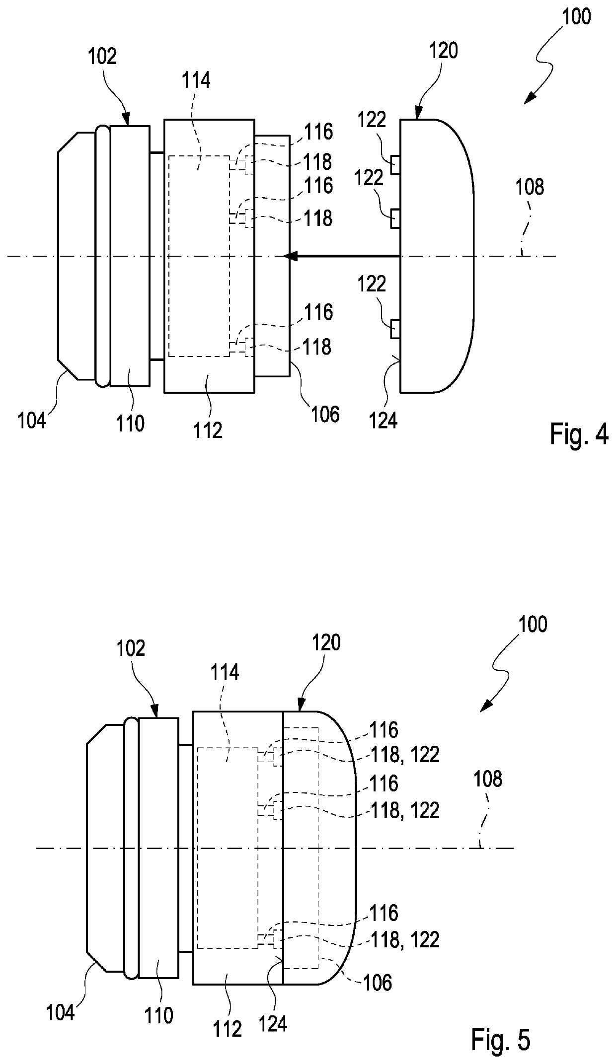
[0097]FIG. 5 shows a side view of the dose recording device 100 according to the second embodiment with an identifier member 120 mounted on the device housing 102. In order to mount the identifier member 120 to the device housing 102, it is simply moved or pressed axially with respect to the longitudinal axis 108 from the rear end 106. Thereby, the actuation members 122 are inserted into some of the holes 118 and actuate some of the switches 116 located at the end of the holes 118 while other switches 116 are not actuated because no corresponding actuation member 122 is inserted into the associated hole 118. An actuation of predetermined switches 116 causes software instructions of the electronic controller 114 to adjust such that the software runs in a predetermined way. Thereby, the electronic controller 114 provides additional information on the drug such as the type of insulin. If a different identifier member 120 is mounted to the device housing 102, the actuation members 122 thereof are inserted into different holes 118 as the positions thereof differ such that different switches 116 are actuated. Thereby, different additional information is provided.
LIST OF REFERENCE NUMBERS
[0098]100 dose recording device
[0099]102 device housing
[0100]104 front end
[0101]106 rear end
[0102]108 longitudinal axis
[0103]110 first part
[0104]112 second part
[0105]114 electronic controller
[0106]116 switch
[0107]118 hole
[0108]120 identifier member
[0109]122 actuation member
[0110]124 front surface
PUM


Description & Claims & Application Information
We can also present the details of the Description, Claims and Application information to help users get a comprehensive understanding of the technical details of the patent, such as background art, summary of invention, brief description of drawings, description of embodiments, and other original content. On the other hand, users can also determine the specific scope of protection of the technology through the list of claims; as well as understand the changes in the life cycle of the technology with the presentation of the patent timeline. Login to view more.