Surveying Instrument

a technology of surveying instruments and inclination sensors, applied in the direction of surveying with inclination sensors, using reradiation, instruments, etc., can solve the problems of inability to accurately measure the reference point, the reference direction, the reference point cannot be highly accurate, etc., to achieve high accuracy of measurement, magnification and distortion of images, and rapid optical axis deflection

Pending Publication Date: 2022-07-21
KK TOPCON
View PDF0 Cites 2 Cited by
  • Summary
  • Abstract
  • Description
  • Claims
  • Application Information

AI Technical Summary

Benefits of technology

[0011]According to the present invention, a surveying instrument is configured to include a distance measuring light projecting module configured to project a distance measuring light along a distance measuring optical axis, a light receiving module configured to receive a reflected distance measuring light, a distance measurement arithmetic module configured to measure a distance to an object and the reflection intensity of the reflected distance measuring light based on a transmission signal of the distance measuring light and a light reception signal of the reflected distance measuring light, a narrow-angle image pickup module configured to have a narrow-angle image pickup optical axis partially shared with the distance measuring optical axis and acquire an image with the distance measuring optical axis as a center, an optical axis deflector configured to have a wavelength dispersion compensation prism arranged in a shared portion of the distance measuring optical axis and the narrow-angle image pickup optical axis and a rotating shaft vertical or substantially vertical with respect to incidence / projection end faces of the wavelength dispersion compensation prism and deflect the distance measuring optical axis by the rotation of the wavelength dispersion compensation prism, an extracting means configured to extract an end face reflection image of the wavelength dispersion compensation prism from the image, and an arithmetic control module configured to control the optical axis deflector and the distance measurement arithmetic module and calculate a deflecting direction of the optical axis deflector based on the end face reflection image extracted by the extracting means. As a result, the optical axis deflection is performed by the wavelength dispersion compensation prism, the rapid optical axis deflection is enabled performed by the small inertial force of the rotating portions, the magnification and distortions of the image can be corrected, an influence of fluctuations of the wavelength dispersion compensation prism can be removed, and the highly accurate measurement can be realized.

Problems solved by technology

Further, in the conventional total station, for the sighting or the detection of the reflecting object, the main body itself must be directed toward an object, and the rapid measurement cannot be performed.
On the other hand, since the laser scanner does not have a function for the sighting using the telescope (narrow-angle) or the detection of the reflecting object, a reference direction, a reference point, or a measuring point cannot be highly accurately measured.

Method used


Image

  • Surveying Instrument
  • Surveying Instrument
  • Surveying Instrument

Examples


first embodiment

[0023]A description will be given on a surveying instrument according to the present invention by referring to FIG. 1 to FIG. 3

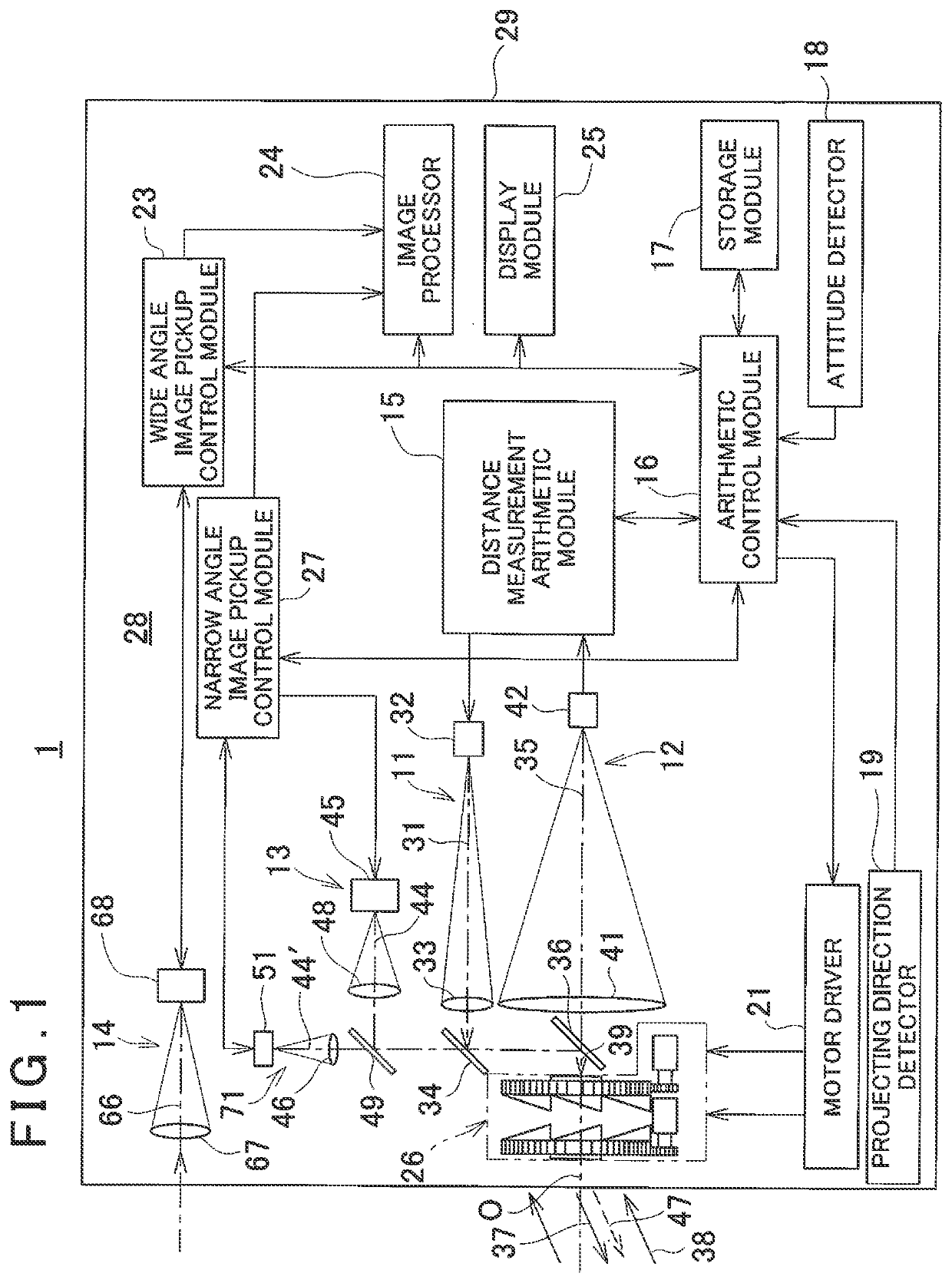
[0024]A surveying instrument 1 mainly includes a distance measuring light projecting module 11, a light receiving module 12, a detecting light projecting module 13, a wide-angle image pickup module 14, a narrow-angle image pickup module 71, a distance measurement arithmetic module 15, an arithmetic control module 16, a storage module 17, an attitude detector 18, a projecting direction detector 19, a motor driver 21, a wide angle image pickup control module 23, an image processor 24, a display module 25, an optical axis deflector 26, and a narrow angle image pickup control module 27. They are accommodated and integrated in a casing 29. It is to be noted that the distance measuring light projecting module 11, the light receiving module 12, the distance measurement arithmetic module 15, the optical axis deflector 26 and the like constitute a distance measuring ...

second embodiment

[0105]Next, by referring to FIG. 10A to FIG. 10C, a description will be given on the present invention. It is to be noted that, in FIG. 10A to FIG. 10C, the same components as shown in FIG. 9A to FIG. 9D are referred by the same symbols, and a description thereof will be omitted.

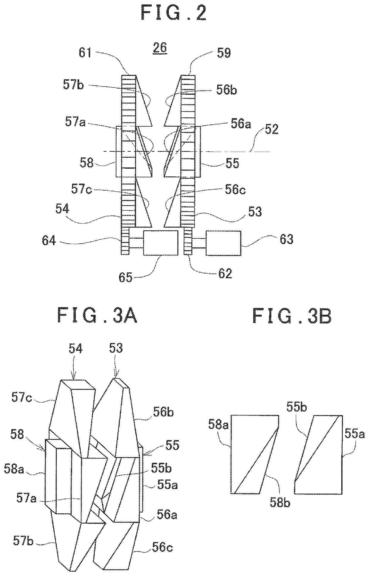
[0106]In the first embodiment, the distance measuring light 37 and the detecting light 47 enter the incidence end face portion of the wavelength dispersion compensation prism 55, which constitutes the optical axis deflector 26, coaxially with the deflection reference optical axis “O”, and the light receiving optical axis 35 is also coaxial with the deflection reference optical axis “O” (see FIG. 1 and FIG. 2). In this case, the object reflection image reflected on the object, the incidence end face reflection images Mr1, Tr1 of the wavelength dispersion compensation prism 55, and the projection end face reflection images Mr2, Tr2 of the wavelength dispersion compensation prism 58 overlap, respectively, and e...


PUM


Abstract

There is provided a surveying instrument including a distance measurement arithmetic module configured to measure a distance to an object and the reflection intensity of a reflected distance measuring light based on a distance measuring light and the reflected distance measuring light, a narrow-angle image pickup module configured to acquire an image with an axis of the distance measuring optical as a center, an optical axis deflector configured to have a wavelength dispersion compensation prism arranged in the distance measuring optical axis and deflect the distance measuring optical axis by the rotation of the wavelength dispersion compensation prism, an extracting means configured to extract an end face reflection image of the wavelength dispersion compensation prism from the image, and an arithmetic control module configured to calculate a deflecting direction of the optical axis deflector based on the end face reflection image extracted by the extracting means.

Description

BACKGROUND OF THE INVENTION[0001]The present invention relates to a surveying instrument having functions of a total station or a laser scanner.[0002]As surveying instruments, there are total stations which enable the prism distance measurement or non-prism distance measurement or laser scanners which perform the distance measurement while scanning an object. In these surveying instruments, to determine a position of a surveying instrument main body, the sighting in a reference direction, or a reference point or a measuring point using a reflecting object such as a retro-reflector must be highly accurately measured. For this reason, the sighting using the telescope (narrow-angle) or the detection of the reflecting object is required.[0003]In a general total station having a telescope, a highly-accurate rotating shaft is required. Therefore, a size and a weight of the surveying instrument main body increase. Further, in the conventional total station, for the sighting or the detectio...

Claims


Application Information

Patent Timeline
Patent Type & Authority Applications(United States)
IPC IPC(8): G01S17/42G01C15/00G01C9/06G01S17/89
CPCG01S17/42G01C15/008G01C2009/066G01S17/89G01C9/06G01C15/002G01S7/4817
Inventor OHTOMO, FUMIOKUMAGAI, KAORUISHINABE, IKUO
Owner KK TOPCON
Why Eureka
Try Eureka