

Tool with surfaces with a compressive surface stress layer
a stress layer and ratchet tool technology, applied in the field of tools, can solve the problems of increasing the size of the tool, increasing the amount of space in the cavity of the head portion of the tool, and affecting the life of the tool, so as to improve the life of wear and fatigue, increase the size and/or expensive manufacturing costs, and improve the effect of wear and fatigue li
- Summary
- Abstract
- Description
- Claims
- Application Information
AI Technical Summary
Benefits of technology
Problems solved by technology
Method used
Image

Examples
Embodiment Construction
[0014]While the present invention is susceptible of embodiments in many different forms, there is shown in the drawings, and will herein be described in detail, embodiments of the invention, including a preferred embodiment, with the understanding that the present disclosure is to be considered as an exemplification of the principles of the present invention and is not intended to limit the broad aspect of the invention to any one or more embodiments illustrated herein. As used herein, the term “present invention” is not intended to limit the scope of the claimed invention, but is instead used to discuss exemplary embodiments of the invention for explanatory purposes only.
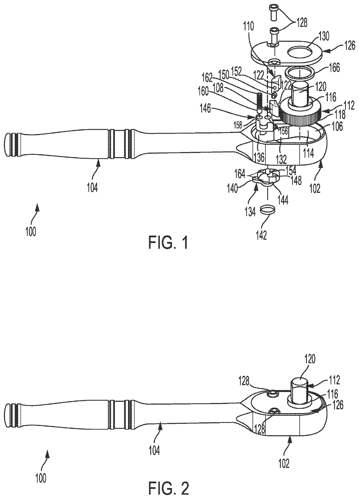
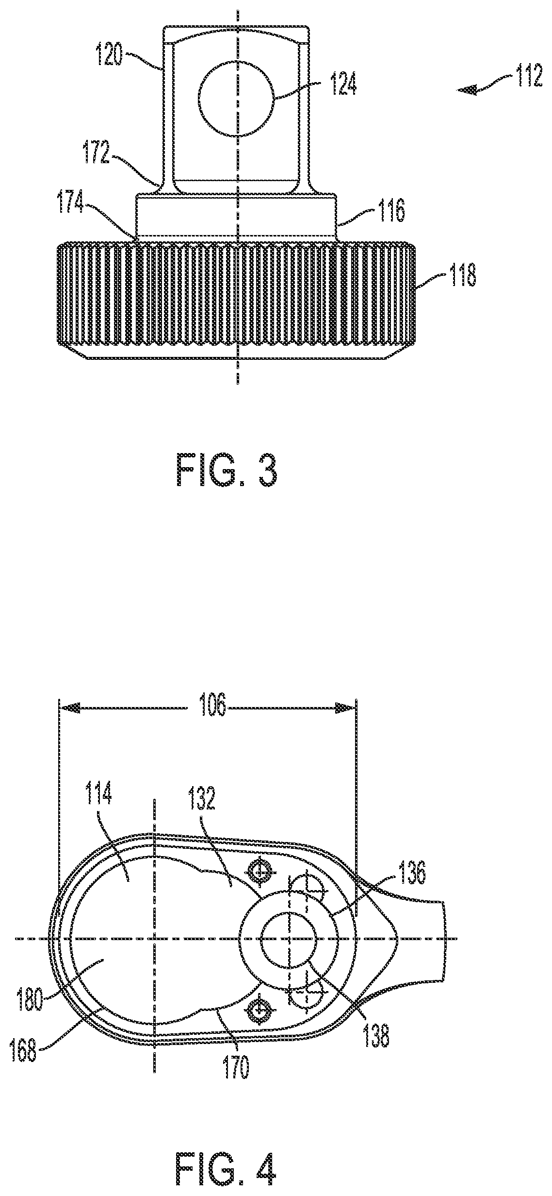
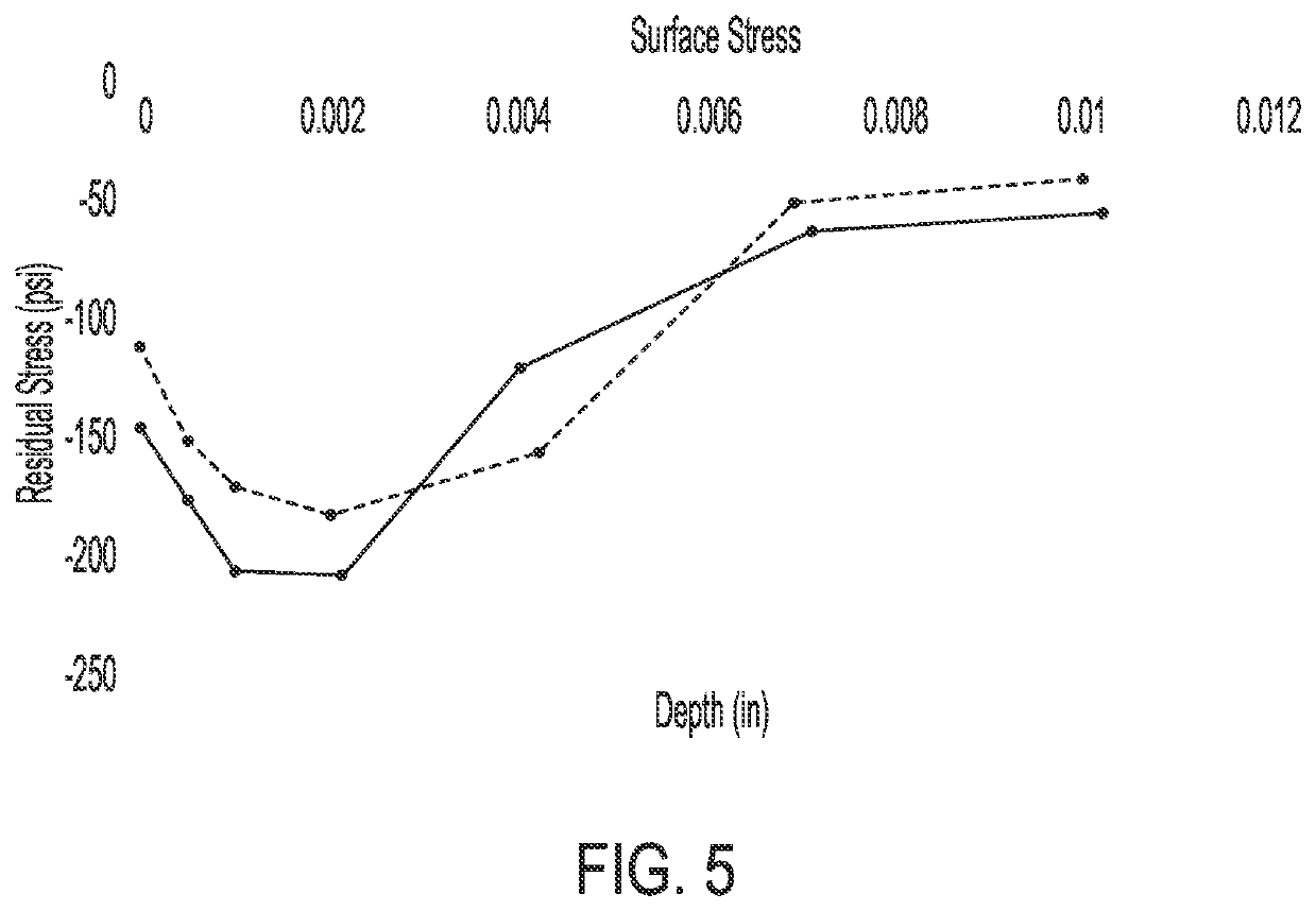
[0015]The present invention broadly includes a tool, such as a ratchet tool, having a head portion with a cavity that is adapted to at least partially contain a ratchet gear. The ratchet tool has surfaces provided with a compressive residual stress layer via a cold working process, such as, for example, shot peenin...
PUM
| Property | Measurement | Unit |
|---|---|---|
| depth | aaaaa | aaaaa |
| depth | aaaaa | aaaaa |
| torque | aaaaa | aaaaa |
Abstract
Description
Claims
Application Information