Motorized Wheelbarrow

a motorized wheel and wheel body technology, applied in the direction of braking systems, transportation items, gearing, etc., can solve the problem of not being able to connect the clutch assembly, and achieve the effect of low risk of inadvertent movemen

Active Publication Date: 2022-07-28
MADNESS MASCH MFG INC
View PDF4 Cites 2 Cited by
  • Summary
  • Abstract
  • Description
  • Claims
  • Application Information

AI Technical Summary

Benefits of technology

[0005]Due to their mutual functional exclusivity, it is not possible for the clutch assembly to be in the connected condition at the same time as the brake assembly is in the engaged condition thereof. As a result, the extent to which the components of the clutch assembly and the brake assembly are subjected to wear is significantly reduced, as compared to the typical prior art unit.
[0006]The mutual functional exclusivity of the clutch assembly and the brake assembly is also a safety feature, as there is a very low risk of inadvertent movement of the clutch assembly to its connected condition.

Problems solved by technology

Due to their mutual functional exclusivity, it is not possible for the clutch assembly to be in the connected condition at the same time as the brake assembly is in the engaged condition thereof.

Method used


Image

  • Motorized Wheelbarrow
  • Motorized Wheelbarrow
  • Motorized Wheelbarrow

Examples


Embodiment Construction

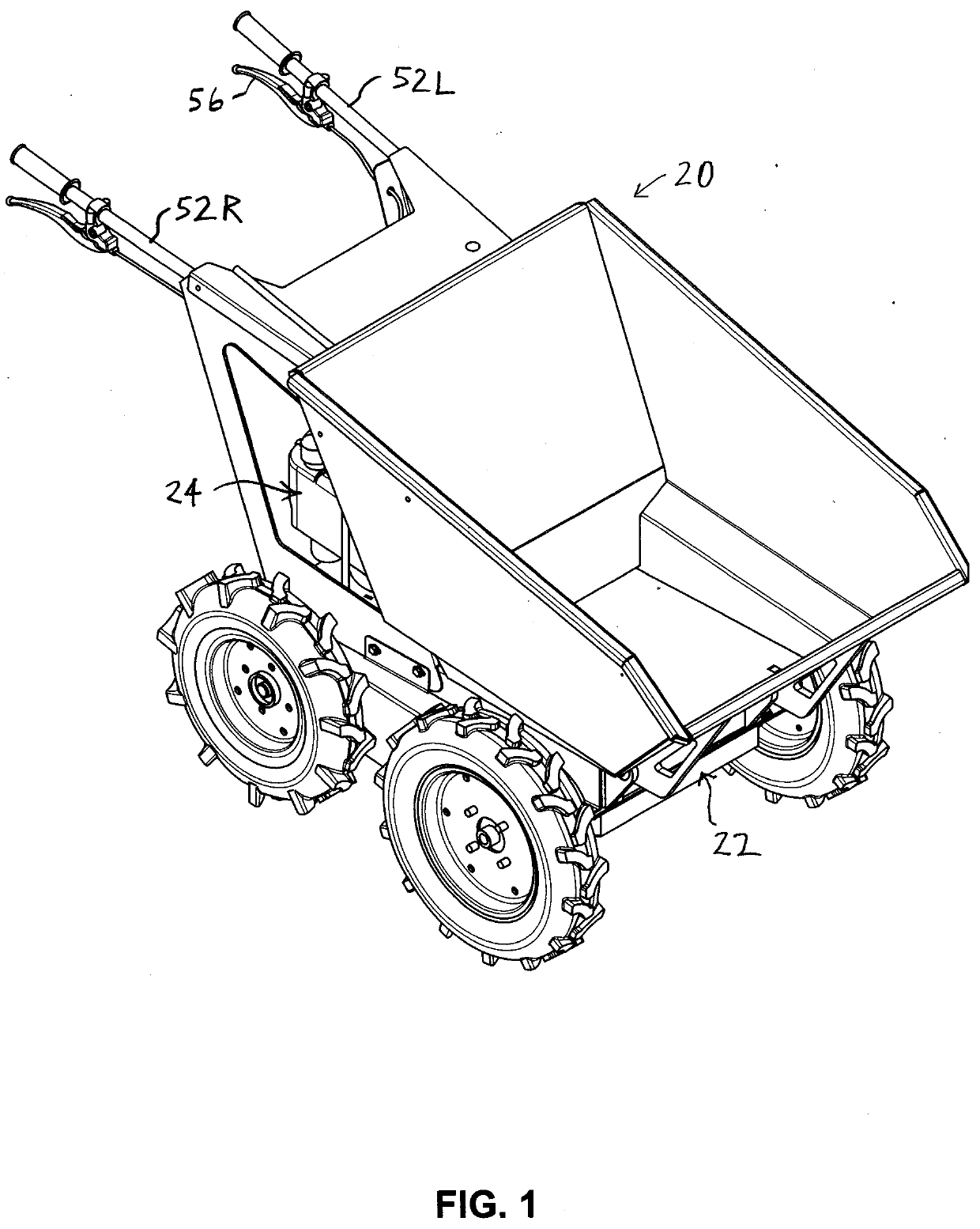
[0038]In the attached drawings, like reference numerals designate corresponding elements throughout. Reference is made to FIGS. 1-9F to describe an embodiment of a motorized wheelbarrow in accordance with the invention indicated generally by the numeral 20.

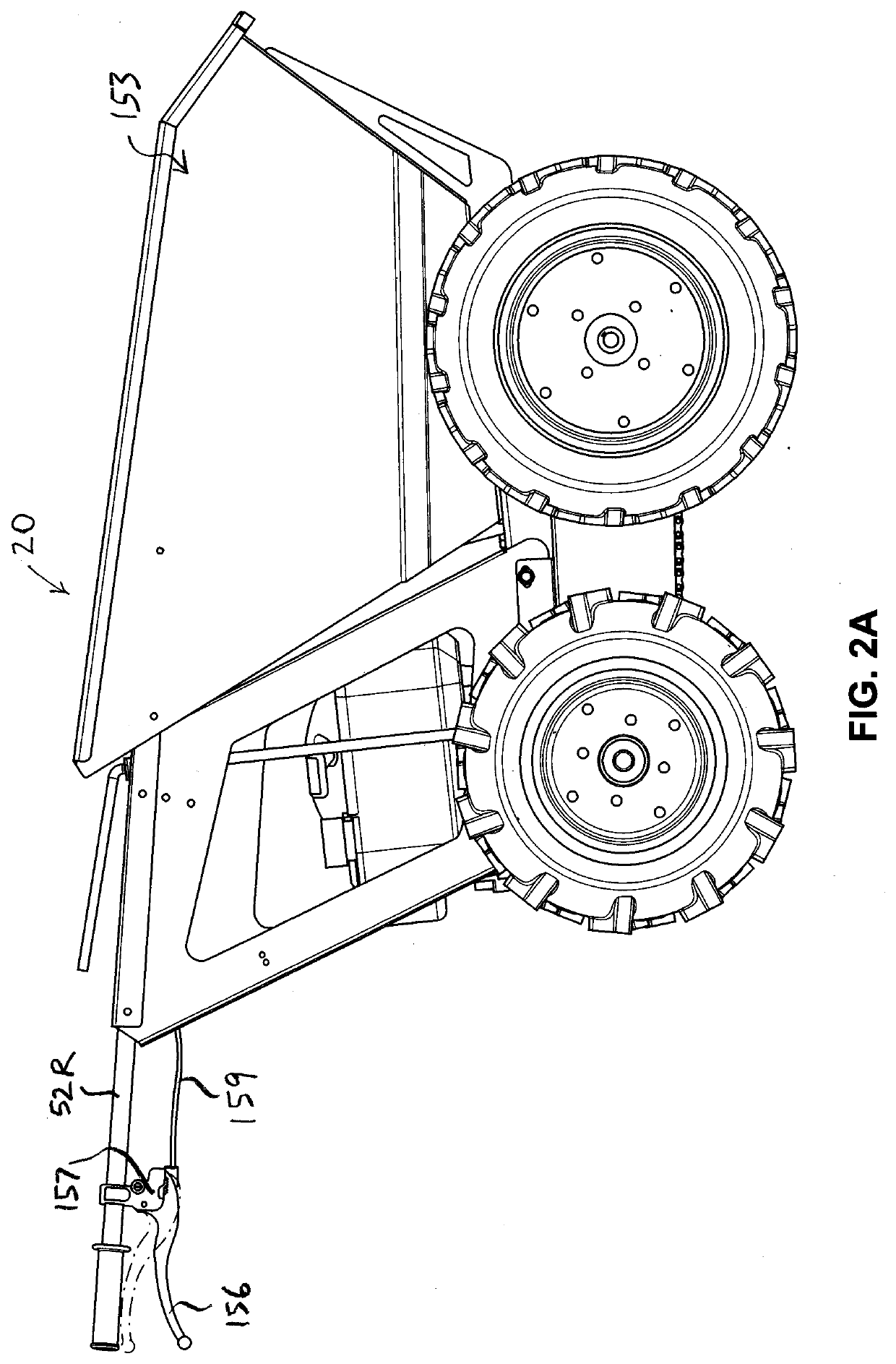
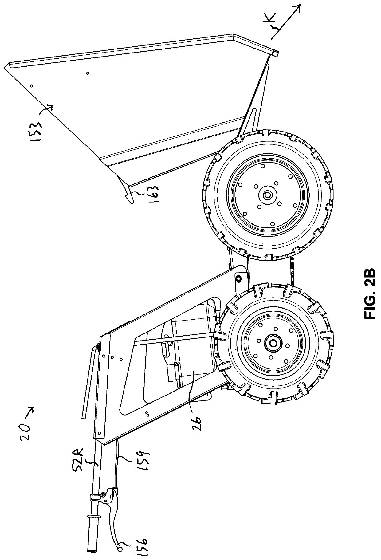
[0039]In one embodiment, the motorized wheelbarrow 20 preferably includes a frame assembly 22, and a motor assembly 24 mounted to the frame assembly 22 (FIG. 1). As will be described, the motor assembly 24 preferably includes a motor 26 (FIGS. 2A, 2B, 6) and a drive pulley 28 (FIG. 7B) that rotates when the motor 26 is operating.

[0040]It is also preferred that the motorized wheelbarrow 20 includes a wheel assembly 30 (FIGS. 1, 7A). The wheel assembly 30 preferably includes front and rear axles 32, 34 that are mounted to the frame assembly 22 (FIG. 7B). As can be seen in FIG. 7B, the front and rear axles 32, 34 define respective front and rear axes “XF” and “XR”. Preferably, the wheel assembly 30 also includes four wheels, includin...


PUM


Abstract

A motorized wheelbarrow including a motor and a drive pulley that rotates when the motor is operating. The motorized wheelbarrow also includes wheels and a drive train assembly for transmitting power from the motor to the wheels. The motorized wheelbarrow also includes a clutch assembly movable between a connected condition, in which the motor and the drive train assembly are connected by the clutch assembly, and a disconnected condition, in which the motor and the drive train assembly are not connected with each other, and a brake assembly movable between an engaged condition, in which the brake assembly resists rotation of the wheels, and a disengaged condition, in which the brake assembly does not resist rotation of the wheels. Both of the clutch assembly and the brake assembly are controlled by a single control assembly so that the clutch assembly and the brake assembly are mutually functionally exclusive.

Description

FIELD OF THE INVENTION[0001]The present invention is a motorized wheelbarrow.BACKGROUND OF THE INVENTION[0002]In the prior art, motorized wheelbarrows have a number of disadvantages. For example, the controls for engaging the drive train and for engaging brakes are typically separate, which often results in an operator causing the clutch to be engaged at the same time as the brake is engaged. Consequently, in the prior art motorized wheelbarrows, certain components are frequently subjected to significant wear, causing premature brake failure, and / or premature failure of other components.SUMMARY OF THE INVENTION[0003]For the foregoing reasons, there is a need for a motorized wheelbarrow that overcomes or mitigates one or more of the defects and disadvantages of the prior art.[0004]In its broad aspect, the invention provides a motorized wheelbarrow including a motor and a drive pulley that rotates when the motor is operating. The motorized wheelbarrow also includes wheels and a drive ...

Claims


Application Information

Patent Timeline
Patent Type & Authority Applications(United States)
IPC IPC(8): B60P1/28B60K23/02B60T7/10B60K17/356F16H7/06F16D67/00F16H7/12
CPCB60P1/286B60K23/02B60T7/102F16H7/1281F16H7/06F16D67/00B60K17/356B60P1/06B60P1/28B60T1/062B60Y2200/225B60K1/00B60K17/02B60K17/342F16H7/0827F16H2007/0893F16H2007/0897F16H2007/0865F16H7/02B62B5/0046
Inventor SKIKAVICH, VINCENT
Owner MADNESS MASCH MFG INC
Why Eureka
Try Eureka