Check patentability & draft patents in minutes with Patsnap Eureka AI!

Diagnosis circuit, electronic device, and diagnosis method

Active Publication Date: 2022-08-04
PANASONIC INTELLECTUAL PROPERTY MANAGEMENT CO LTD
View PDF16 Cites 0 Cited by
  • Summary
  • Abstract
  • Description
  • Claims
  • Application Information

AI Technical Summary

Benefits of technology

The demand for more definition and resolution in electronic devices is increasing, as is the amount of data being processed by digital signal processing. This means that the size of the multiplexer, which is used to select data, needs to be larger. This patent aims to address this issue.

Problems solved by technology

Besides, in digital signal processing, as the computational complexity further increases to realize an even higher definition, the number of data elements to process and the number of multiplexers for use to select data also increase.

Method used


Image

  • Diagnosis circuit, electronic device, and diagnosis method
  • Diagnosis circuit, electronic device, and diagnosis method
  • Diagnosis circuit, electronic device, and diagnosis method

Examples


embodiments

[0015](1) Overview

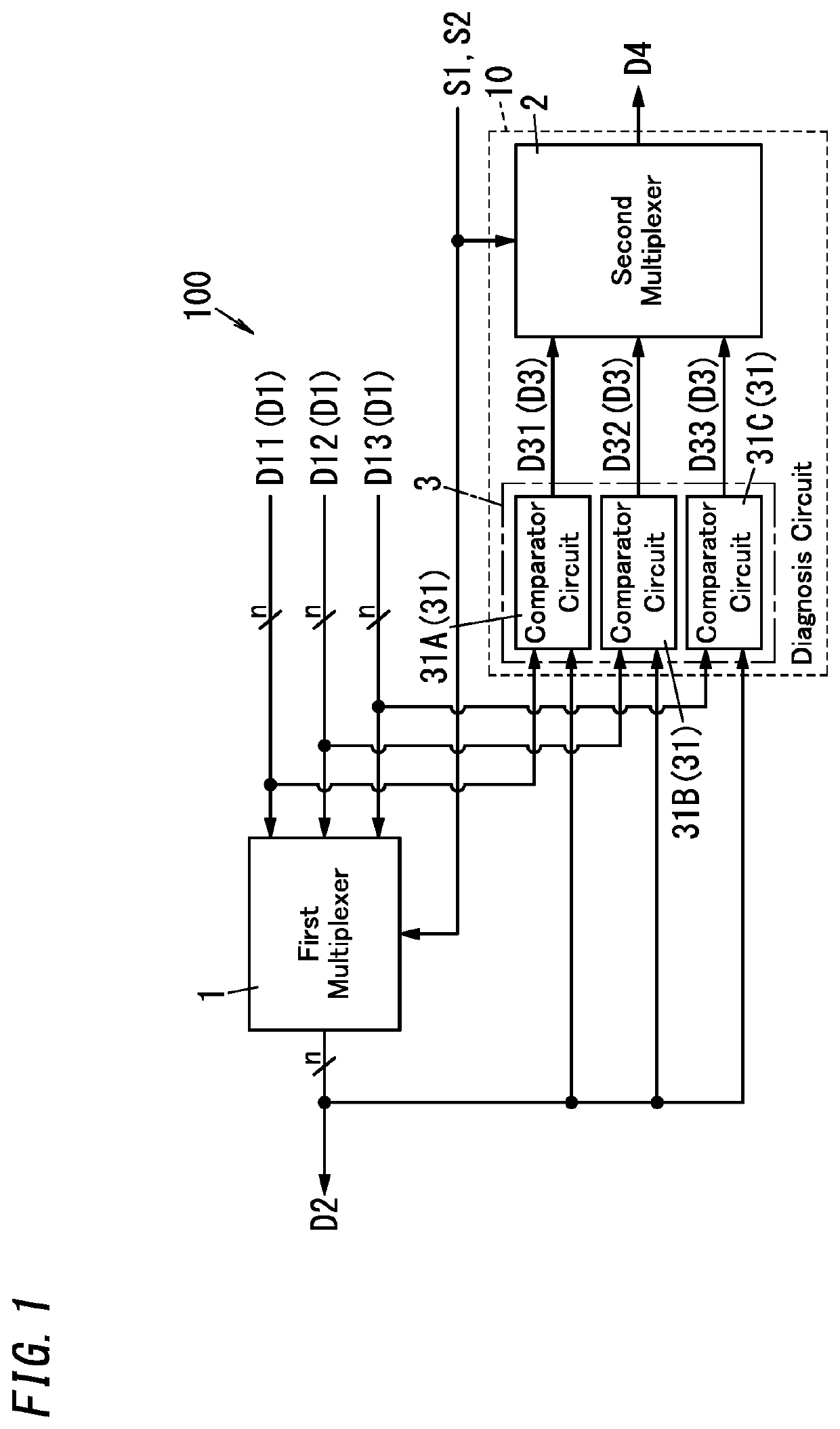
[0016]First, an overview of a diagnosis circuit 10 and electronic device 100 according to an exemplary embodiment will be described with reference to FIG. 1.

[0017]A diagnosis circuit 10 according to an exemplary embodiment may be used in an electronic device 100. The electronic device 100 may be, for example, an acceleration sensor for detecting acceleration or an angular velocity sensor (gyrosensor) for detecting an angular velocity. In this embodiment, the electronic device 100 may be implemented as an acceleration sensor, for example. The electronic device 100 includes a first multiplexer 1 and the diagnosis circuit 10 as shown in FIG. 1. The first multiplexer 1 receives a plurality of (e.g., three) input data elements D1 and selectively outputs one of the plurality of input data elements D1 as a selected data element D2. Each of the plurality of input data elements D1 and the selected data element D2 is data of n1 bits, where n1 is a natural number equal to or ...


PUM


Abstract

A diagnosis circuit makes a diagnosis of a first multiplexer. The first multiplexer receives input data elements, selects one of the input data elements, and outputs the selected one as a selected data element. The diagnosis circuit includes a comparator unit and a second multiplexer. The comparator unit compares each of the input data elements to be supplied to the first multiplexer with the selected data element provided by the first multiplexer. The second multiplexer receives comparative data elements corresponding one to one to results of comparison made by the comparator unit with respect to the input data elements and outputs, out of the comparative data elements, a comparative data element, including a result of comparison between the one input data element selected by the first multiplexer and the selected data element, as a result data element.

Description

CROSS-REFERENCE TO RELATED APPLICATIONS[0001]The present application is based upon, and claims the benefit of priority to, Japanese Patent Application No. 2021-014595, filed on Feb. 1, 2021, the entire contents of which are hereby incorporated by reference.TECHNICAL FIELD[0002]The present disclosure generally relates to a diagnosis circuit, an electronic device, and a diagnosis method. More particularly, the present disclosure relates to a diagnosis circuit for making a diagnosis of a multiplexer, an electronic device including the diagnosis circuit, and a diagnosis method to be used by the diagnosis circuit.BACKGROUND ART[0003]JP 2015-142431 A discloses a storage battery monitoring device for monitoring a storage battery in which a plurality of battery cells are connected in series. The storage battery monitoring device of JP 2015-142431 A turns a plurality of balancing switches to make any one of the plurality of battery cells discharging while keeping the other battery cells disc...

Claims


Application Information

Patent Timeline
IPC IPC(8): G06F11/26
CPCG06F11/26G01R31/36G06F11/22
Inventor NAGAI, MASAAKI
Owner PANASONIC INTELLECTUAL PROPERTY MANAGEMENT CO LTD
Features
  • R&D
  • Intellectual Property
  • Life Sciences
  • Materials
  • Tech Scout
  • Unparalleled Data Quality
  • Higher Quality Content
  • 60% Fewer Hallucinations
Learn More