
Refrigerating appliance and water outlet arrangement for a refrigerating appliance

Pending Publication Date: 2022-08-11
BSH BOSCH & SIEMENS HAUSGERAETE GMBH
View PDF0 Cites 1 Cited by
  • Summary
  • Abstract
  • Description
  • Claims
  • Application Information

AI Technical Summary

Benefits of technology

The invention prevents foam from displaceing the water outlet arrangement on a refrigerated goods container. This is achieved by ensuring that the foam pressure of the insulating material does not disrupt the capillary action of the water outlet arrangement. Additionally, the tube facility is securely bonded or screwed to the wall region, creating a stable connection.

Problems solved by technology

The consequence would otherwise be an intense loss of the insulating effect and in certain circumstances a freezing of the water drain.
A precise positioning by the contour that is further remote from the outlet is difficult on account of the flat angle and the gap and it is possible for the positioning to be displaced by the foaming pressure during the customary foaming for the production of the insulation.
There is a risk of water leakage to the foam on account of parts that lie close to one another and the so-called capillary action.
In addition, material expansions take place on account of different temperatures and put a strain on the adhesive connection.
In the case of metal parts, the design flexibility is limited, in the case of plastic parts made from fireproof material, the material selection is reduced and expensive.
The processing tools and recycling are complex.

Method used


Image

  • Refrigerating appliance and water outlet arrangement for a refrigerating appliance
  • Refrigerating appliance and water outlet arrangement for a refrigerating appliance
  • Refrigerating appliance and water outlet arrangement for a refrigerating appliance

Examples


first embodiment

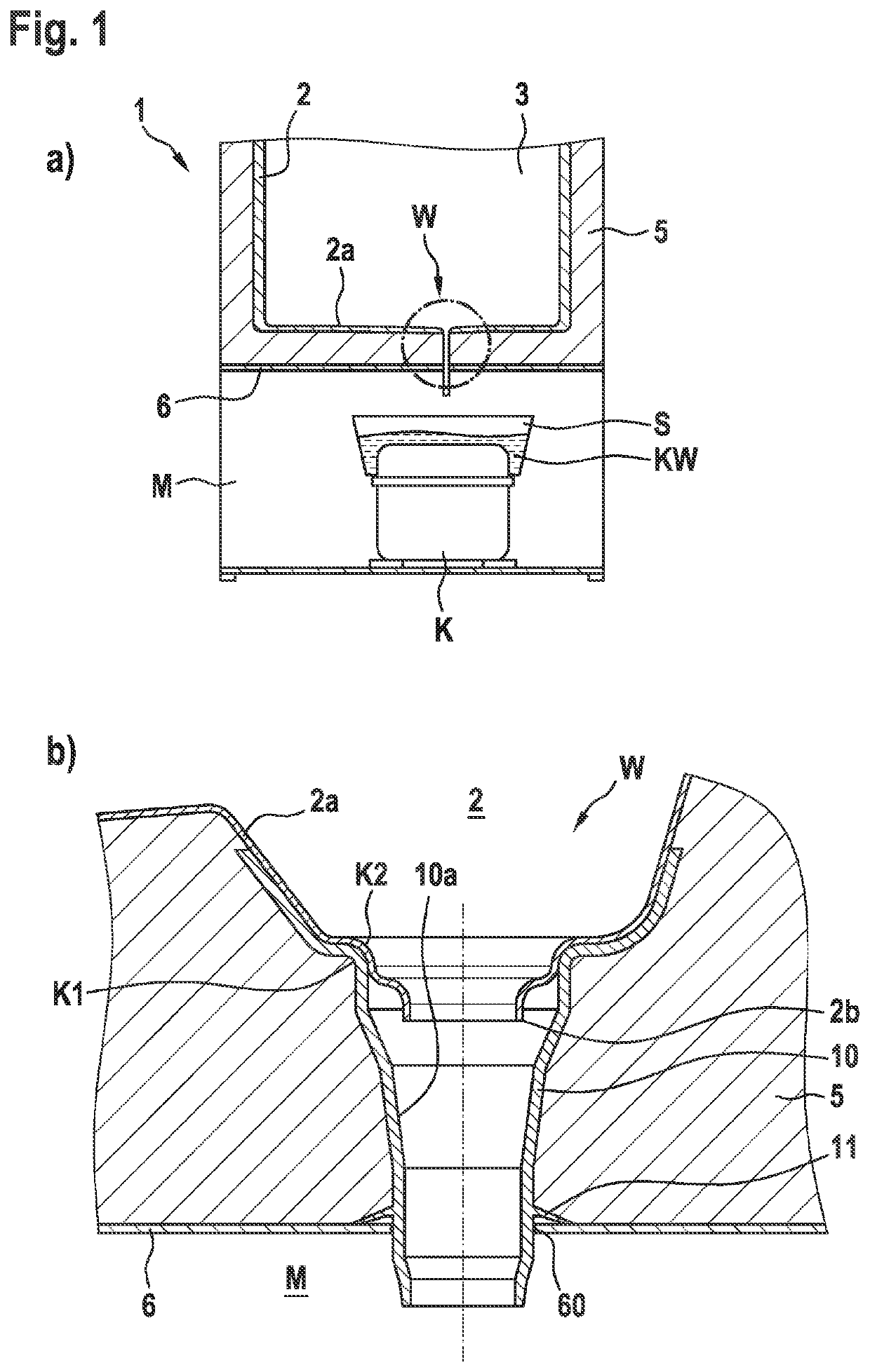
[0033]FIGS. 1a), b) shows schematic cross-sectional illustrations of a refrigeration appliance and a water outlet arrangement that is provided therein in accordance with the invention.

[0034]The refrigeration appliance 1 that is illustrated in FIG. 1a), in particular a household refrigeration appliance, has a refrigerated goods container 2 that encompasses a refrigerating zone 3 for refrigerated goods.

[0035]Condensation water KW that is collected in the refrigerated goods container 2 of the refrigeration appliance 1 is guided via a water outlet arrangement W (only illustrated schematically in FIG. 1a)) into an evaporation container S that is located in a machine compartment M above a compressor K, in which evaporation container the condensation water KW is evaporated to the outside atmosphere.

[0036]The water outlet arrangement W that is illustrated in detail in FIG. 1b) guides the condensation water KW from the refrigerated goods container 2 through a tub-shaped wall region 2a of the...

second embodiment

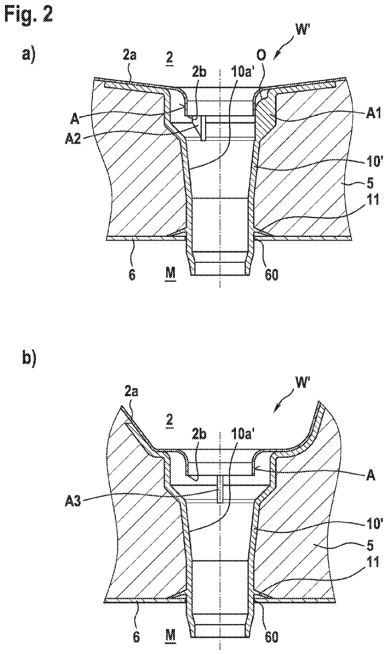
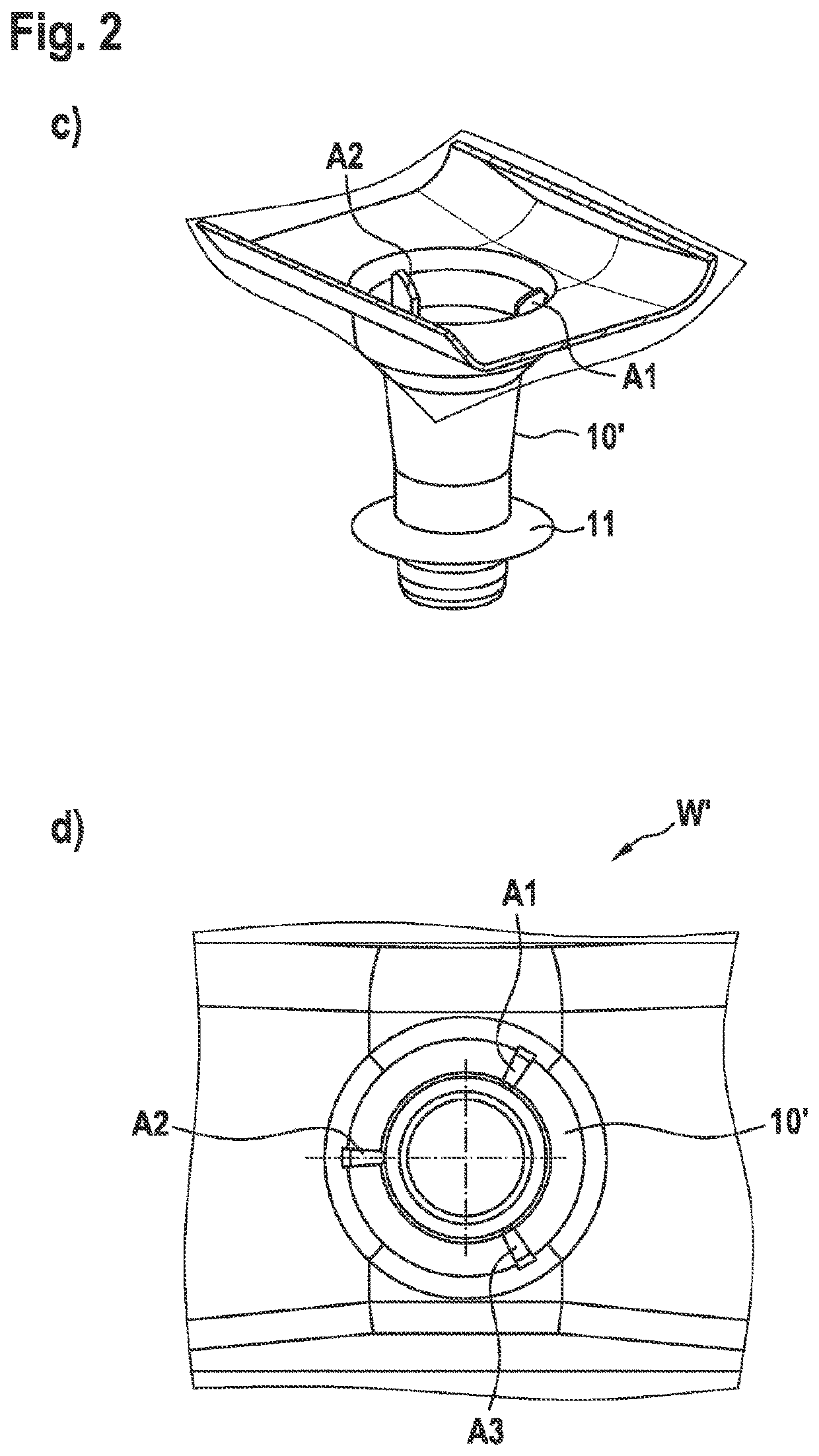
[0044]FIG. 2a)-d) illustrate schematic illustrations of a water outlet arrangement in accordance with the invention, and namely FIGS. 2a), b) in a cross-sectional view and FIG. 2c) in a perspective view and FIG. 2d) in a plan view.

[0045]The water outlet arrangement W′ in accordance with the second embodiment differs from the first embodiment in the design of the positioning facility A1, A2, A3 for the drip edge 2b.

[0046]A tube 10′ which is connected to the wall region 2a and also the wall region 2a in the case of the second embodiment do not have repeatedly curved surface contour regions.

[0047]On the contrary, a spacing facility is provided as a positioning facility A1, A2, A3 and said spacing facility has a plurality of ribs A1, A2, A3 that are oriented radially starting from the inner wall 10a′ of the tube 10′ into the interior of the tube and are arranged resting against an outer side A of the wall region 2a.

[0048]The plurality of ribs A1, A2, A3 extend axially in the interior ...

third embodiment

[0050]FIG. 3a)-d) illustrate schematic illustrations of a water outlet arrangement in accordance with the invention and namely FIGS. 3a), b) in a cross-sectional view and FIG. 3c) in a perspective view and FIG. 3d) in a plan view.

[0051]The water outlet arrangement W″ in accordance with the third embodiment likewise comprises a positioning facility A1′-A6′ in the form of a spacing facility which comprises a plurality of ribs A1′-A6′ which are however oriented in a curved manner starting from the inner wall 10a″ into the interior of the tube 10″ and are arranged resting against the outer side A of the wall region 2a.

[0052]In the case of this embodiment, the plurality of ribs A1′-A6′ also extend axially in the interior of the tube 10″ as far as the drip edge 2b and are spaced on their upper side O from the wall region 2a.

[0053]Moreover, an elastic tolerance compensation against thickness fluctuations of the shaped refrigerated goods container 2 is provided by the curvature of the rib...


PUM


Abstract

A refrigerating appliance, or household refrigerating appliance, includes a refrigerated goods container and a machine compartment having a wall facing the goods container, an insulating material region between the goods container and the machine compartment wall, and a water outlet arrangement conducting condensate from the goods container through the insulating material region and machine compartment wall into an evaporation container in the machine compartment. The water outlet arrangement has a trough-shaped wall region of the goods container oriented towards the machine compartment wall and extending funnel-like to a drip edge. A tube facility extends from the wall region through the insulating material region and an opening in the machine compartment wall into the machine compartment. A positioning device mutually positions the wall region and tube facility, securing the drip edge radially in the tube facility and circumferentially spaced from an inner wall of the tube facility.

Description

[0001]The invention relates to a refrigeration appliance, in particular a household refrigeration appliance, for example a refrigerator, and also a water outlet arrangement for a refrigeration appliance.PRIOR ART[0002]In the case of customary refrigeration appliances, condensation water that is collected in a refrigerated goods container of the refrigeration appliance is guided via a water outlet arrangement into an evaporation container that is located in a machine compartment, in which evaporation container said condensation is evaporated to the outside atmosphere.[0003]During the operation of refrigeration appliances and freezers, due to the air humidity that is located in the cooling compartment, condensation water accumulates and must be drained through the insulation out of the appliance to the outside.[0004]For this purpose, a water outlet component is attached to the refrigeration appliance inner container. It is necessary to ensure at the connecting site of the two componen...

Claims


Application Information

Patent Timeline
IPC IPC(8): F25D21/14F25D23/06
CPCF25D21/14F25D2321/146F25D2321/143F25D23/061F25D2321/141F25D23/06
Inventor KOCH, ALEXANDERWESER, RAINER
Owner BSH BOSCH & SIEMENS HAUSGERAETE GMBH
Learn More