Self-registering, -squaring, and -supporting mount apparatus and method

a technology of self-registering and supporting mounts, applied in the installation of lighting conductors, electrical cable installations, constructions, etc., can solve the problems of requiring rework or sloppy, detracting from the silhouette or other appearance of a building or other protected structure, and sloppy squaring

Pending Publication Date: 2022-08-25
VFC GRP LLC
View PDF0 Cites 0 Cited by
  • Summary
  • Abstract
  • Description
  • Claims
  • Application Information

AI Technical Summary

Problems solved by technology

Failure to register (position at a pre-determined location, typically translation, linear in any or all dimensions) any mounting system, secure it in place, and install a poin

Method used


Image

  • Self-registering, -squaring, and -supporting mount apparatus and method
  • Self-registering, -squaring, and -supporting mount apparatus and method
  • Self-registering, -squaring, and -supporting mount apparatus and method

Examples


Embodiment Construction

[0071]It will be readily understood that the components of the present invention, as generally described and illustrated in the drawings herein, could be arranged and designed in a wide variety of different configurations. Thus, the following more detailed description of the embodiments of the system and method of the present invention, as represented in the drawings, is not intended to limit the scope of the invention, as claimed, but is merely representative of various embodiments of the invention. The illustrated embodiments of the invention will be best understood by reference to the drawings, wherein like parts are designated by like numerals throughout.

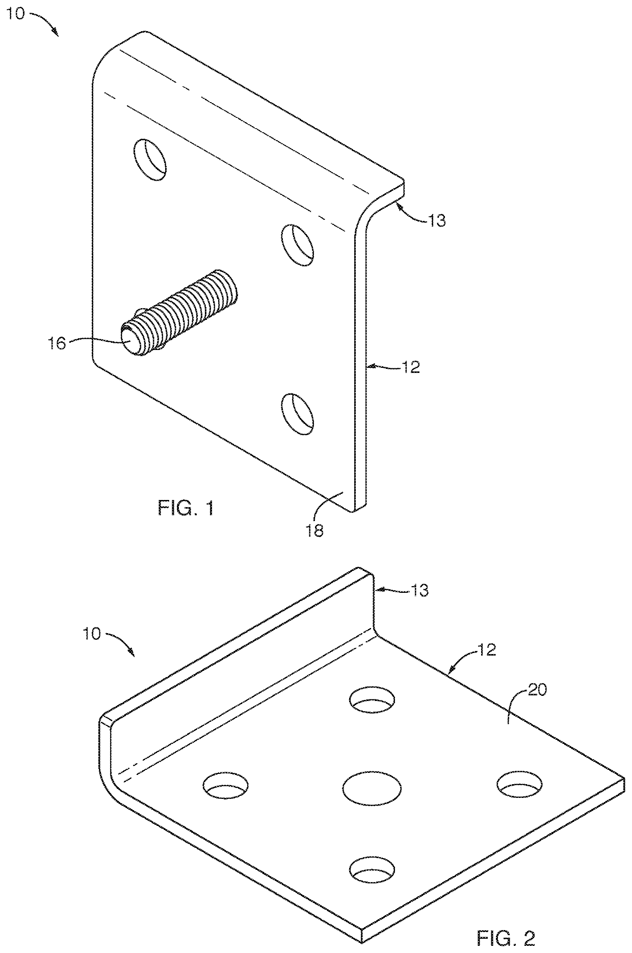
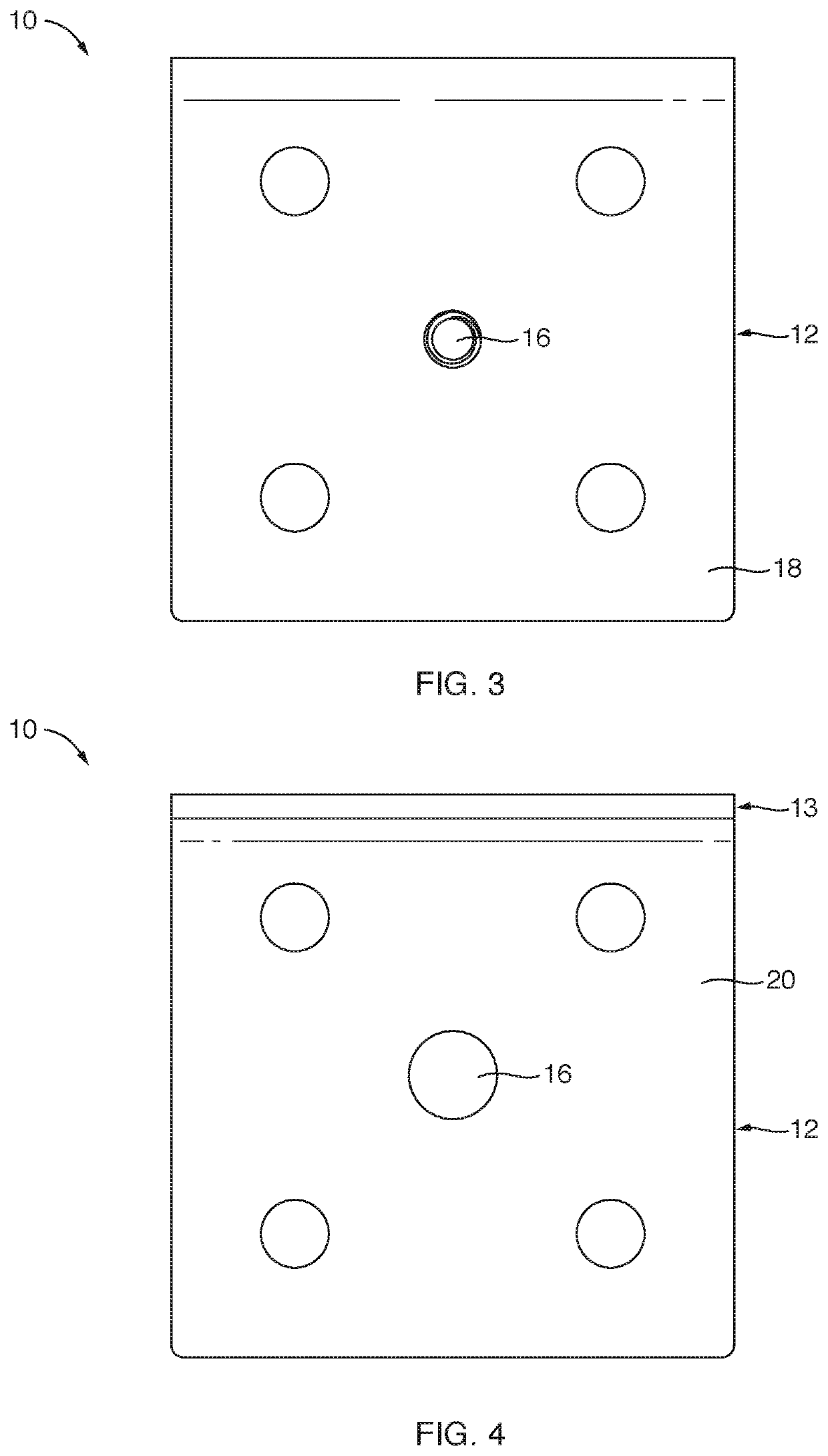
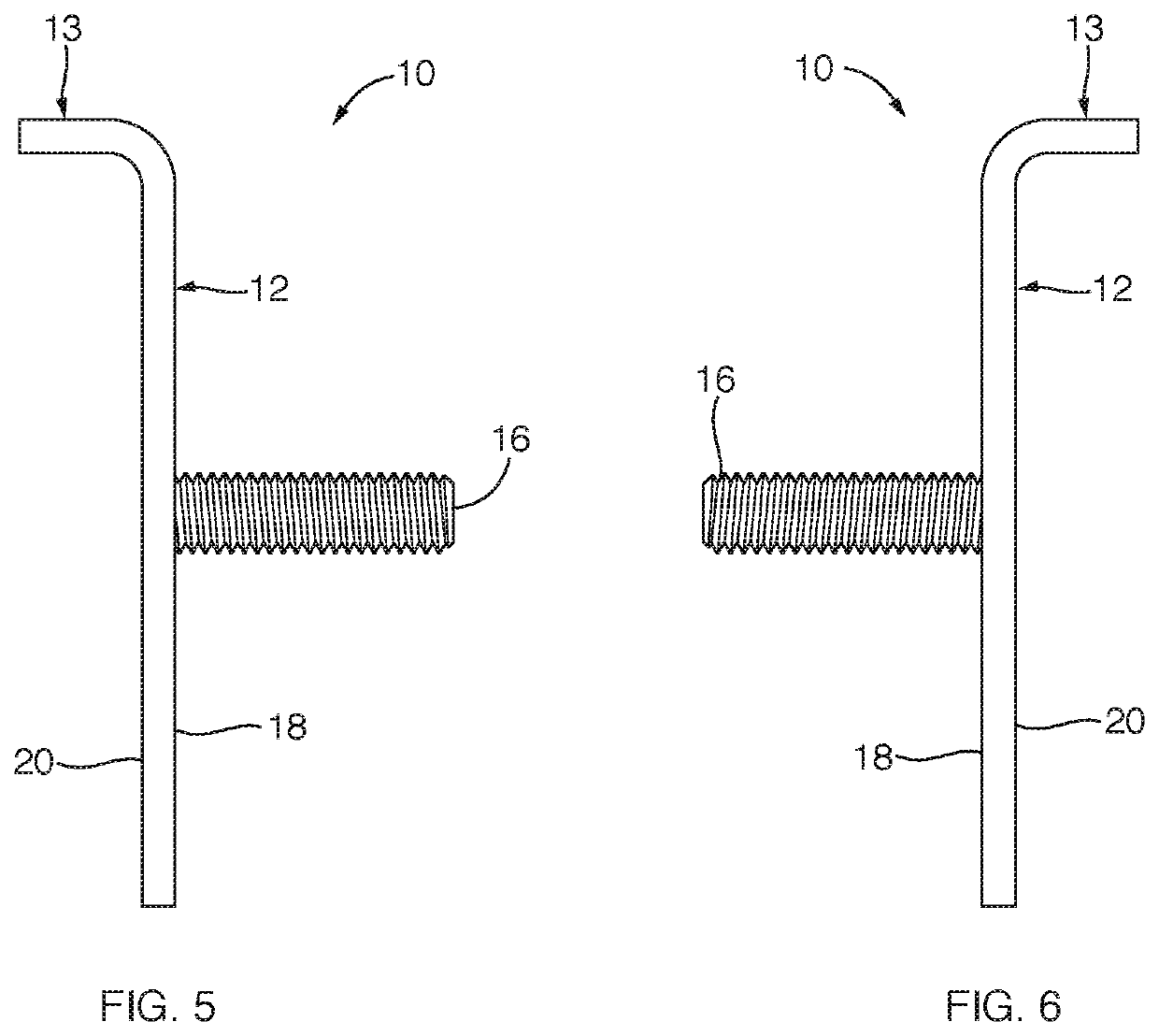
[0072]Referring to FIGS. 1 through 8 illustrating various views of a base plate 12 with a lip13, and FIGS. 1 through 21 generally, an anchor 10 or anchor system 10 may include a base plate 12 designed to secure to a surface layer 11, an edge thereof, typically a right angle fold line in a protective layer 11 on a building 17. In...


PUM


Abstract

An anchor for components of a lightning protection system may rely on a bonding agent, such as an adhesive, needing time for curing, drying, or otherwise setting (increasing in adhesion, strength, mechanical stability, or any combination thereof) by remaining in place while setting. The anchor may be suspended by a lip extending horizontally past an edge (plane of intersection of two planar surfaces) where a base plate is adhered to a vertical surface and the lip rests, registers in translation, and squares in rotation against a horizontal surface sharing an edge or fold (corner, bend) with the vertical surface. Once set sufficiently, the adhesive supports loads in shear (along plane of adhesion) and tension (perpendicular to plane of adhesion) imposed by brackets holding a cable, point, or both at each base plate.

Description

RELATED APPLICATIONS[0001]This application claims the benefit of co-pending U.S. Provisional Patent Application Ser. No. 63 / 153,769, which is hereby incorporated herein by reference in its entirety, including any appendices filed therewith. This application hereby incorporates herein by reference U.S. Pat. No. 10,135,233 issued Nov. 20, 2018; U.S. Pat. No. 9,263,864; and U.S. Pat. No. 8,950,055; all of which are incorporated herein by reference in their entirety.FIELD OF THE INVENTION[0002]This invention relates to lightning protection systems and, more particularly, to novel systems and methods for mounting and anchoring cables and points (air terminals) thereof.BACKGROUND ART[0003]Lightning arresters are central to power systems. Typical power delivery and transmission systems involve towers or power poles holding long expanses of power-carrying cables high above the surface of the earth and across large tracts of land. The power delivery systems of the public utilities create a g...

Claims


Application Information

Patent Timeline
IPC IPC(8): E04B1/92
CPCE04B1/92H02G13/40H02G13/00
Inventor PARTRIDGE, KIRKVOUGHT, TODDVOUGHT, TRAVIS
Owner VFC GRP LLC
Why Eureka
Try Eureka