Eureka AIR delivers breakthrough ideas for toughest innovation challenges, trusted by R&D personnel around the world.

Process and apparatus for monitoring and/or controlling an air conditioning and/or heating plant

a technology for monitoring and/or controlling an air conditioner and/or heating plant, which is applied in the direction of heating types, instruments, program control, etc., can solve the problems of difficult to recognize if the plant is operating properly, affecting the overall management cost, and complex tasks for controlling and optimizing air conditioning and/or heating plants

Pending Publication Date: 2022-08-25
FIMCIM
View PDF0 Cites 0 Cited by
  • Summary
  • Abstract
  • Description
  • Claims
  • Application Information

AI Technical Summary

Benefits of technology

The invention aims to control air conditioning and heating plants to optimize energy exchange and prevent poor efficiency operating conditions. Additionally, the invention provides a process and device to detect and model the plant behavior, allowing effective monitoring of the plant. The invention also enables optimal adjustment of carrier fluid parameters, reducing load losses and heat losses.

Problems solved by technology

The control and optimization of air conditioning and / or heating plants are rather complex tasks, especially when there are numerous environments served by the same plant, as it happens in plants for offices, hotels, or buildings in which numerous separate environments are present, where the carrier fluid must be transported in the optimal temperature and flow rate conditions so as to ensure an efficient and optimized thermal exchange.
It is evident that the efficiency of the energy exchange in each environment and the mode for controlling the main parameters of the carrier fluid affect the efficiency of the plant in its entirety and hence impact the overall management costs.
Finally, in addition to an intrinsic control complexity given by the multiplicity of environment served by the same plant, it is also very difficult to recognize if the plant is actually working in an optimal manner and hence close to its ideal work conditions, or if on the other hand there are problems tied to a progressive deterioration of the performances or inefficiencies tied for example to an erroneous use of one or more terminals (e.g. partially obstructed or damaged exchangers).
The known technical solutions have often shown to be unsuitable in monitoring the behavior of the plant and in controlling the carrier fluid, actually forcing the plant to operate in non-optimal conditions.
A further problem is given by the identification of suitable models which allow representing the behavior of the plant and hence which allow facilitating the monitoring thereof.

Method used


Image

  • Process and apparatus for monitoring and/or controlling an air conditioning and/or heating plant
  • Process and apparatus for monitoring and/or controlling an air conditioning and/or heating plant
  • Process and apparatus for monitoring and/or controlling an air conditioning and/or heating plant

Examples


Embodiment Construction

[0349]Air Conditioning and / or Heating Plant

[0350]With reference to the enclosed figures, reference number 1 overall indicates an air conditioning and / or heating plant.

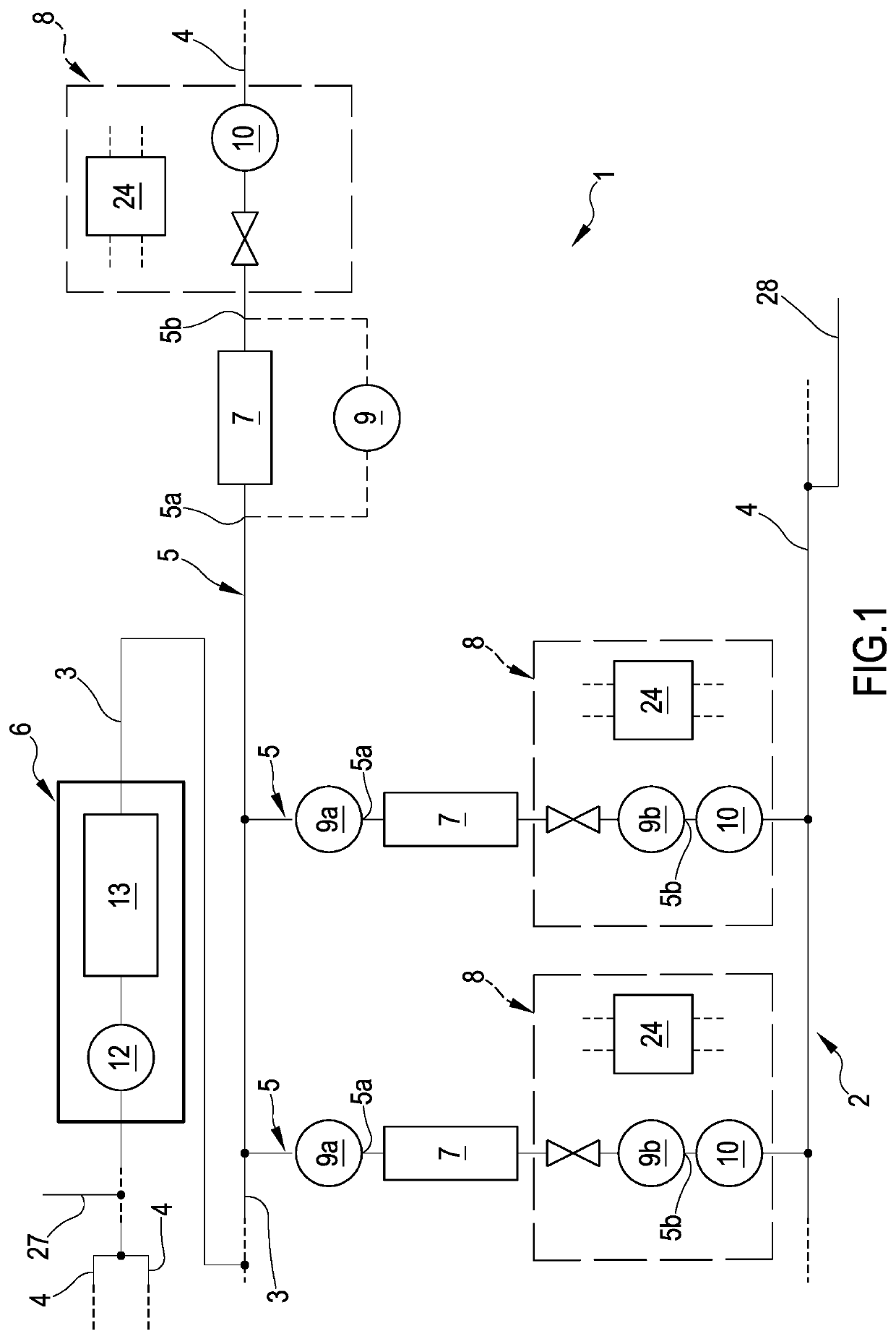
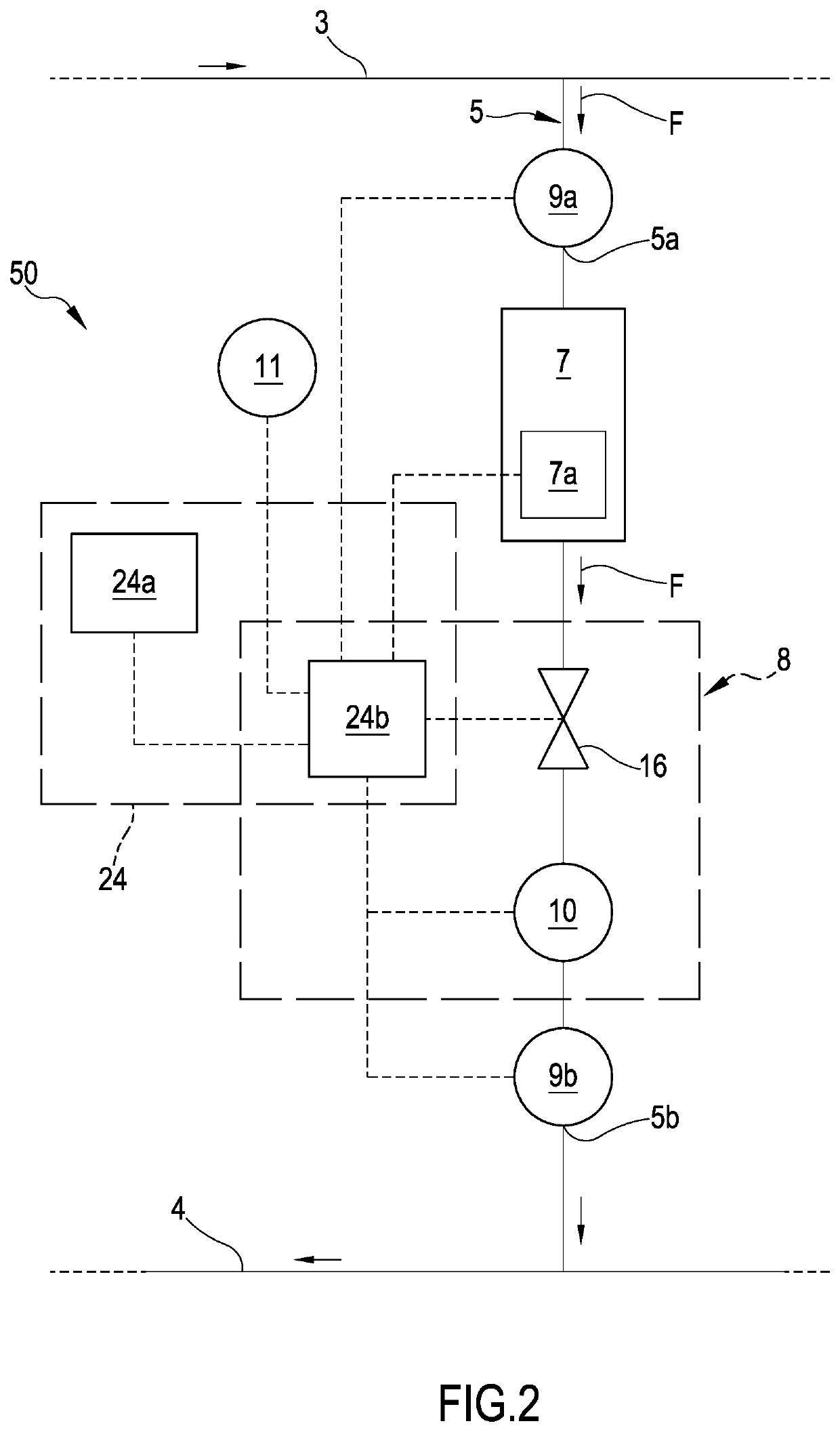
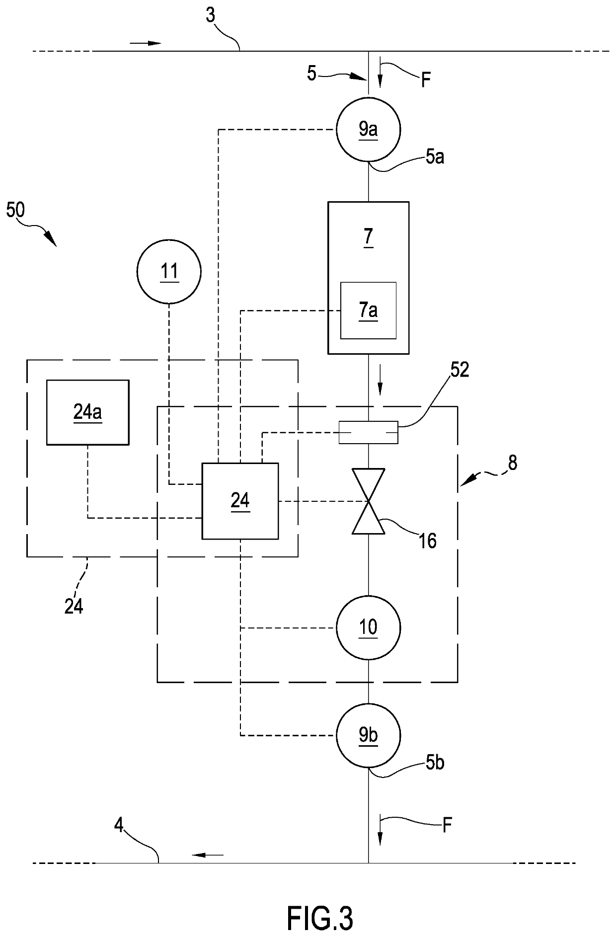
[0351]As is visible for example in FIG. 1, the plant 1 comprises a circuit 2 for distributing a carrier fluid; the circuit 2 has at least two main channels, i.e.: a delivery line 3, for sending the carrier fluid to a predetermined number of users or thermal exchange units 7, and a return line 4 in fluid connection with the delivery line 3 and arranged for receiving the carrier fluid downstream of each of the units 7. As is visible from FIG. 1, the distribution circuit 2 comprises a plurality of circulation channels or service lines 5 directly or indirectly in connection with the delivery line 3 and with the return line 4 and configured for serving respective environments to be air conditioned and / or heated; each service line 5 is configured for supplying at least one respective thermal exchange unit 7. FIG. 1 illustrat...


PUM


Abstract

A process and apparatus for monitoring and / or controlling at least one air conditioning and / or heating plant (1) including a delivery line (3), a return line (4) and service lines (5) hydraulically interposed between the delivery line (3) and the return line (4), each service line (5) comprising at least one thermal exchange unit (7). The process detects a value (φ) of the flow rate of the carrier fluid traversing the thermal exchange unit (7), and determines a temperature difference (ΔT) between the temperature (Tt1) of the carrier fluid, at the first section (5a), detected at a first instant (t1), and the temperature (Tt2) of the carrier fluid, at the second section (5b), detected at a second instant (t2).

Description

FIELD OF THE INVENTION[0001]The invention regards a process of monitoring and / or controlling an air conditioning and / or heating plant, e.g. of HVAC type. In some embodiments, the process and the device according to aspects of the invention can be used for actively controlling or for monitoring parameters such as the fluid flow rate or the temperature of the carrier fluid traversing one or more thermal exchange units constituting an air conditioning and / or heating plant. The invention also regards an air conditioning and / or heating plant using the process and the device according to the invention. The invention is usable both in civil and in industrial fields and advantageously can be exploited for controlling and optimizing the energy level of air conditioning and / or heating plants.STATE OF THE ART[0002]As is known, heating and / or air conditioning plants are increasingly used for maintaining environments, such as home or office rooms, in desired climate conditions, e.g. temperature ...

Claims


Application Information

Patent Timeline
IPC IPC(8): F24F11/63G05B19/042
CPCF24F11/63G05B2219/2614G05B19/042F24D2220/042F24D2220/044F24F11/84F24F2140/12F24F2140/20
Inventor CIMBERIO, ROBERTOGUIDETTI, TIZIANOFREIN, ANTOINE
Owner FIMCIM
Why Eureka
Eureka Blog
Learn More