A vacuum heat collecting tube with helically advancing semi-circumferentially distributed fin bodies

A vacuum heat-collecting tube and half-circle technology, which is applied in the direction of solar heat collectors, solar heat collectors, and solar thermal energy using working fluids. Applicable to problems such as gas heat transfer fluid and fluid viscosity increase, to achieve the effect of promoting high-efficiency conversion, reducing temperature gradient, and optimizing flow field and temperature field

Active Publication Date: 2020-07-14
INST OF ELECTRICAL ENG CHINESE ACAD OF SCI
View PDF12 Cites 0 Cited by
  • Summary
  • Abstract
  • Description
  • Claims
  • Application Information

AI Technical Summary

Problems solved by technology

Chinese invention patent CN102425867A proposes the structure of the trough solar vacuum heat collecting tube with one-sided inner fin, that is, the inner surface of the metal heat absorbing tube focusing on the solar energy is provided with an inner fin, and the heat is transferred to the metal absorbing tube through the inner fin. The center of the heat pipe effectively mixes the fluid on the concentrating side of the heat-absorbing tube with the fluid in the center of the tube, but cannot regulate the disturbance and heat transfer of the fluid on the non-concentrating side
At the same time, this invention is not very suitable for gas as a heat transfer fluid. Because the physical properties of gas are different from that of liquid, as the temperature of the wall surface and inner fins on the concentrating side increases, the viscosity of the fluid increases, and the distribution of fins increases. Increase the flow resistance, so that the fluid gradually flows to the area with less resistance and lower temperature, and the fluid participating in heat exchange on the concentrating side gradually decreases

Method used


Image

  • A vacuum heat collecting tube with helically advancing semi-circumferentially distributed fin bodies
  • A vacuum heat collecting tube with helically advancing semi-circumferentially distributed fin bodies
  • A vacuum heat collecting tube with helically advancing semi-circumferentially distributed fin bodies

Examples


Embodiment Construction

[0028] The present invention will be further described below in conjunction with the accompanying drawings and specific embodiments.

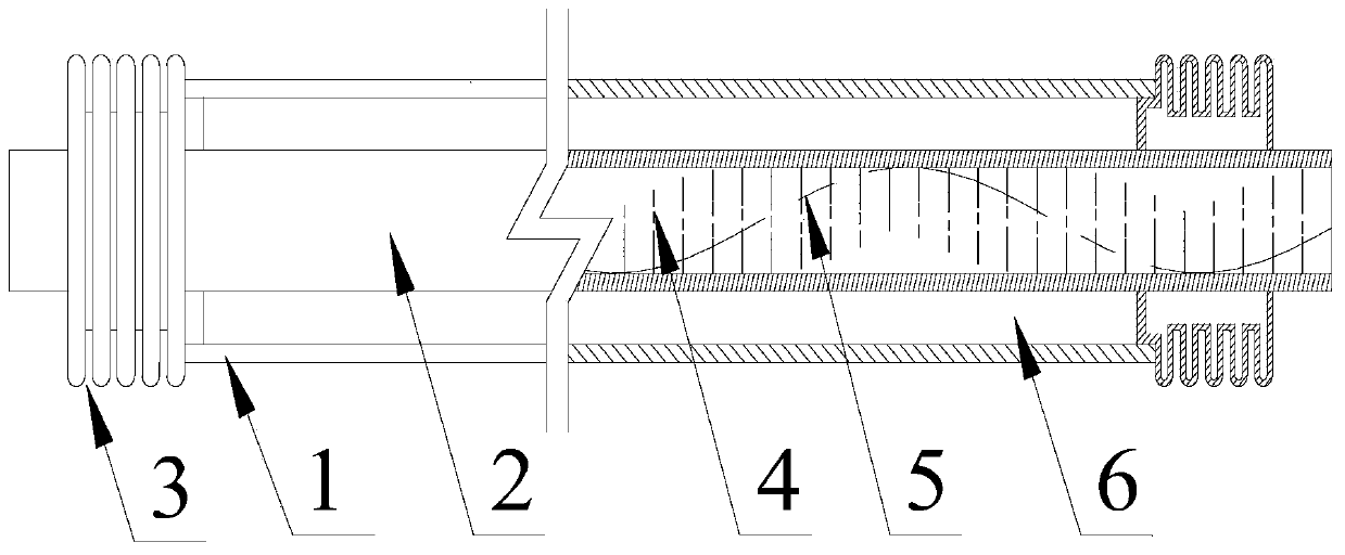
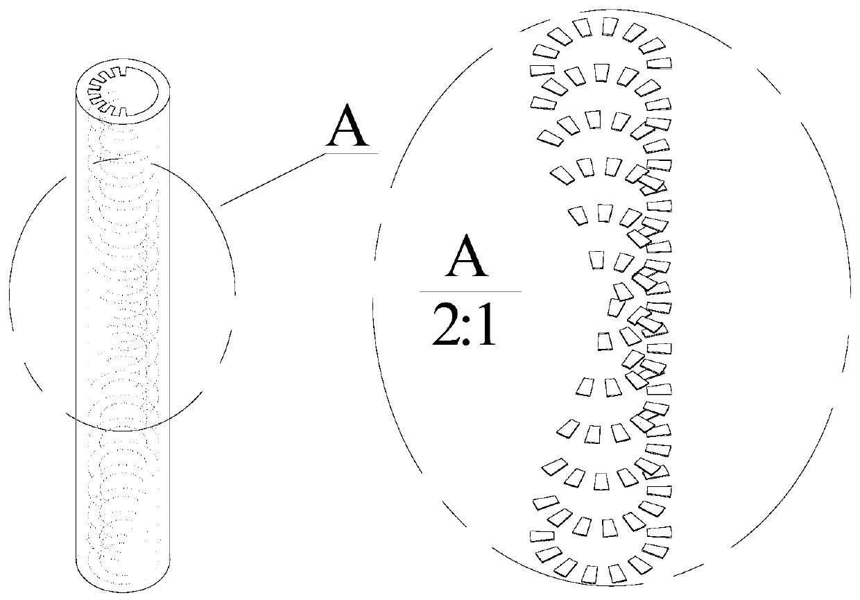
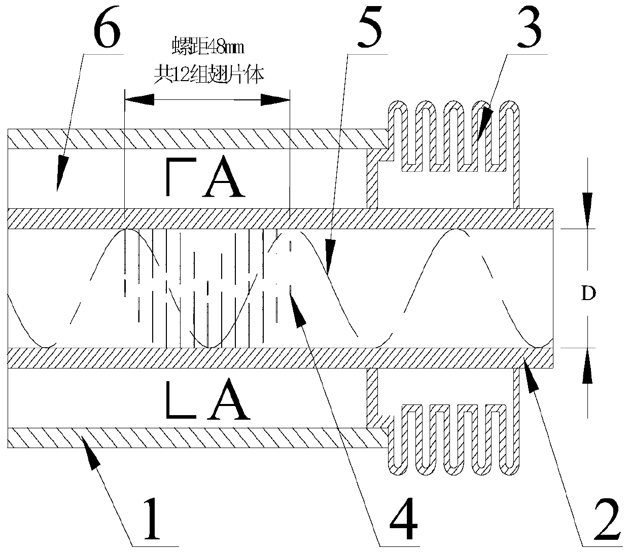
[0029] A vacuum heat-collecting tube with spirally advanced fins distributed on a semi-circumference, comprising a glass outer tube 1 and a metal heat-absorbing tube 2 containing fins 4, the metal heat-absorbing tube 2 is located in the glass outer tube 1, and Shaft arrangement. The glass outer tube 1 is connected with the metal heat absorbing tube 2 through a sealing device, and an expansion joint 3 is arranged at the end of the glass outer tube 1 . A vacuum cavity 6 is formed between the metal heat-absorbing tube 2 and the glass outer tube 1 . The schematic diagram of the distribution of fins in the metal heat absorbing tube is as follows: figure 2 shown.

[0030] One of the embodiments of the heat collecting tube of the present invention is as image 3 shown. The outer wall of the metal heat-absorbing pipe 2 is coated with a selective ...


PUM


Abstract

The invention provides a vacuum collector tube with spirally advancing type semicircular unilateral fin bodies. A glass outer tube (1) and a metal heat absorbing tube (2) comprising the fin bodies (4)are coaxially arranged from outside to inside. A vacuum cavity (6) exists between the glass outer tube (1) and the metal heat absorbing tube (2), and the glass outer tube (1) and the metal heat absorbing tube (2) are connected through a seal device. The end of the metal outer tube (1) is provided with an expansion joint (3). The outer surface of the metal heat absorbing tube (2) is coated with asolar selective absorption coating. The inner surface of the metal heat absorbing tube (2) is provided with the fin bodes (4) which are integrated with the metal heat absorbing tube. The fin bodies (4) are unilaterally arranged on the semicircle of the inner wall of the metal heat absorbing tube and meanwhile arranges and advances in the axial direction of the metal heat absorbing tube in a three-dimensional spiral shape perpendicularly or slantly. The heights h of the fin bodies (4) are constant or vary according to the distribution of high and low energy flow densities. The height of the fin bodies arranged on the side with the high energy flow density is smaller than that of the fin bodies arranged on the side with the low energy flow density.

Description

technical field [0001] The invention relates to a solar vacuum heat collecting tube. Background technique [0002] In solar thermal utilization systems, line-focus concentrating systems, such as parabolic trough and linear Fresnel, can generate energy flux densities as high as tens of kilowatts per square meter or even higher. The heat collecting tube located on the focal plane of the concentrator is an efficient heat conversion component, and the vacuum heat collecting tube in the form of sealing the glass outer tube and the metal heat absorbing tube, and vacuuming the sandwich between the glass outer tube and the metal heat absorbing tube is usually used. The outer wall of the metal heat-absorbing pipe is coated with a selective absorption coating to improve the absorption efficiency of sunlight and reduce radiation heat loss. Due to the solar concentrating characteristics of the concentrator, the heated surface of the vacuum heat collecting tube that receives the concent...

Claims


Application Information

Patent Timeline
Patent Type & Authority Patents(China)
IPC IPC(8): F24S10/40F24S10/75
CPCY02E10/44
Inventor 赵紫薇白凤武张喜良王志峰
Owner INST OF ELECTRICAL ENG CHINESE ACAD OF SCI
Why Eureka
Try Eureka