Battery module

a battery module and battery technology, applied in the field of batteries, can solve the problems of not being able the inability to prevent the loosening of bolts and nuts during use, and the supposed detent at both ends, so as to reduce the weight of the rod-shaped connecting member

Pending Publication Date: 2022-08-25
HONDA MOTOR CO LTD
View PDF0 Cites 0 Cited by
  • Summary
  • Abstract
  • Description
  • Claims
  • Application Information

AI Technical Summary

Benefits of technology

[0005]According to the technique of Patent Document 1, while a battery module is assembled, when restraint rod is fastened with a bolt, deterioration of workability due to rotation of the restraint rod along with rotation of the bolt can be suppressed. However, the technique of Patent Document 1 is not for preventing looseness of bolts and nuts fastening end plates during use of the battery module. That is, since no countermeasure is taken for torsion residual stress that is caused by friction on the thread surface at the time of fastening and remains in the bolt shaft portion, it is impossible to prevent looseness of bolts and nuts during use. Moreover, according to the technique of Patent Document 1, it is not supposed to provide detents at both ends in a case of fastening bolts and nuts at both ends.
[0006]The present invention has been made in view of the aforementioned situation. An object of the present invention is to provide a battery module which can prevent looseness of a rod-shaped member that fastens end plates during use, by minimizing torsion residual stress in the rod-shaped connecting member.
[0010]In the battery module according to (1), the rod-shaped connecting member includes the fastening portion adjacent to one of the two end plates, and the detent mechanism part in the vicinity of the fastening portion. Therefore, at the time of fastening operation, the residual torsion (torsion stress) in the fastening portion is generated limitedly in a section corresponding to the vicinity described above. On the other hand, a major section of the entire length of the rod-shaped connecting member, from the detent mechanism part of the rod-shaped connecting member to the other end plate side, is not affected by displacement around the shaft from the other end plate side. Accordingly, the major section of the entire length of the rod-shaped connecting member has no residual torsion. As a result, it is possible to prevent looseness of the fastening portion of the rod-shaped connecting member during use of the battery module.
[0012]In the battery module according to (3), the rod-shaped connecting member has a smaller diameter in the intermediate portion in the longitudinal direction than in the end portion. Therefore, the weight of the rod-shaped connecting member can be reduced.

Problems solved by technology

However, the technique of Patent Document 1 is not for preventing looseness of bolts and nuts fastening end plates during use of the battery module.
That is, since no countermeasure is taken for torsion residual stress that is caused by friction on the thread surface at the time of fastening and remains in the bolt shaft portion, it is impossible to prevent looseness of bolts and nuts during use.
Moreover, according to the technique of Patent Document 1, it is not supposed to provide detents at both ends in a case of fastening bolts and nuts at both ends.

Method used


Image

  • Battery module
  • Battery module
  • Battery module

Examples


first embodiment

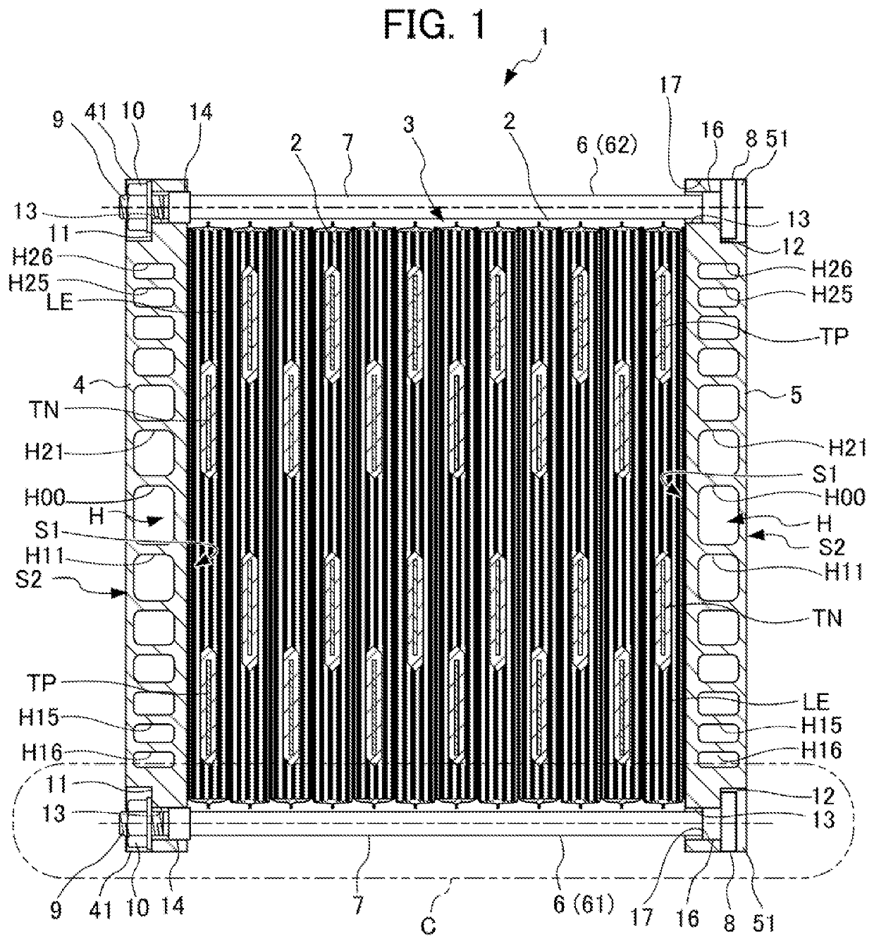
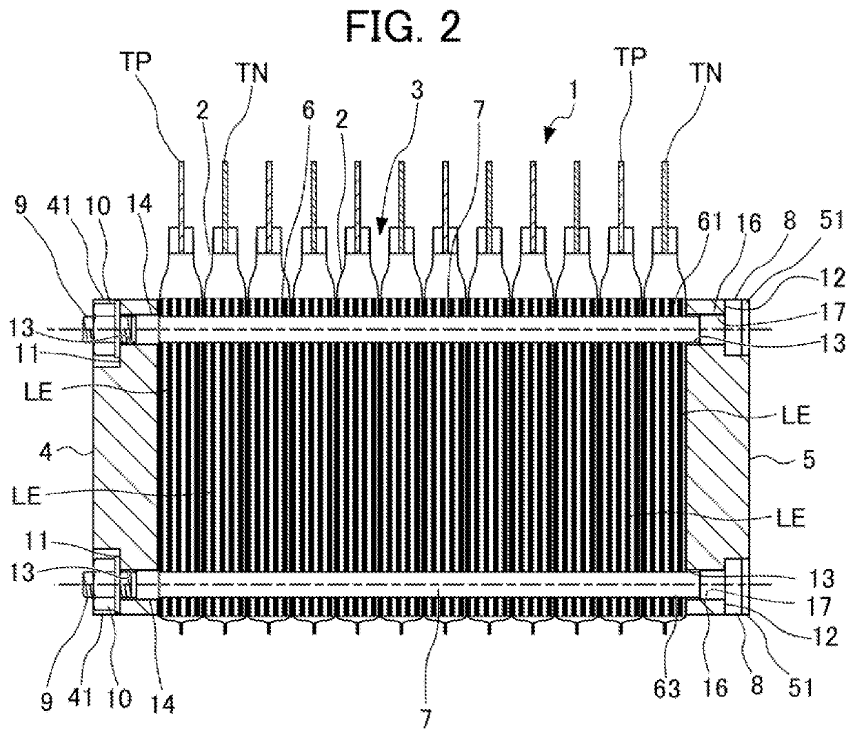
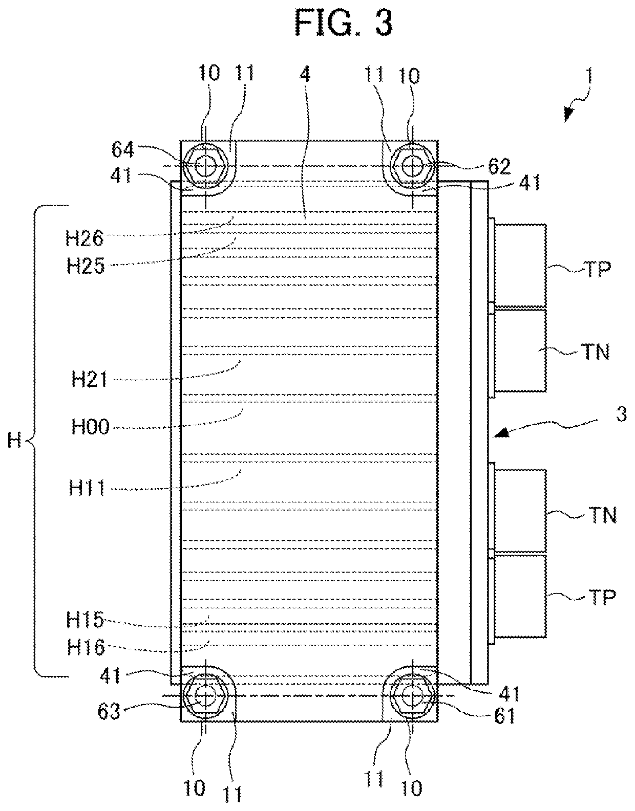
[0041]Next, a first embodiment of the present invention will be described with reference to the drawings. In the drawings shown below, the same components and corresponding components are denoted by the same reference numeral. FIG. 1 is a plan view of a battery module according to a first embodiment of the present invention, FIG. 2 is a side view of the battery module of FIG. 1, FIG. 3 illustrates the battery module of FIG. 1 as viewed from one end plate side, and FIG. 4 illustrates the battery module of FIG. 1 as viewed from the other end plate side.

[0042]A battery module 1 of the first embodiment is configured such that a stacked body 3 of a plurality of battery cells 2 in a flat shape that is a stacked body of laminate pack lithium-ion battery cells is pinched and held by a first end plate 4 and a second end plate 5 from both end sides in the stacking direction. Each battery cell 2 is configured such that a laminated electrodes LE are packed with a laminate sheet, and a positive ...

second embodiment

[0058]Next, a second embodiment of the present invention will be described with reference to FIGS. 10 to 15. FIG. 10 illustrates a portion corresponding to the portion encircled with the circle C in FIG. 1 described above in an enlarged manner, in the second embodiment of the present invention. On the left side in FIG. 10, a portion of the first end plate 4 as viewed from the nut 10 side is illustrated. On the right side in FIG. 10, a portion of the second end plate 5 as viewed from the head portion 8 side is illustrated. FIG. 11 is a cross-sectional view taken along line A-A in FIG. 10. FIG. 12 illustrates the elements in FIG. 11 separately. FIG. 13 is a cross-sectional view taken along line B-B in FIG. 10. FIG. 14 illustrates the elements in FIG. 13 separately. FIG. 15 illustrates surroundings of a detent mechanism in FIG. 10 in an enlarged manner.

[0059]In the first connecting bolt 61, the nut 10 is screwed to the male threaded portion 9 on the first end plate 4 side, and the head...

third embodiment

[0065]Next, a third embodiment of the present invention will be described with reference to FIGS. 16 to 20. FIG. 16 illustrates a portion corresponding to the portion encircled with the circle C in FIG. 1 described above in an enlarged manner, in the third embodiment of the present invention. On the left side in FIG. 16, a portion of the first end plate 4 as viewed from the nut 10 side is illustrated. On the right side in FIG. 16, a portion of the second end plate 5 as viewed from the head portion 8 side is illustrated. FIG. 17 is a cross-sectional view taken along line A-A in FIG. 16. FIG. 18 illustrates the elements in FIG. 17 separately. FIG. 19 is a cross-sectional view taken along line B-B in FIG. 16. FIG. 20 illustrates the elements in FIG. 19 separately.

[0066]In the first connecting bolt 61, the nut 10 is screwed to the male threaded portion 9 on the first end plate 4 side, and the head portion 8 is formed on the second end plate 5 side. The pressing force from the nut 10 act...


PUM

PropertyMeasurementUnit
friction coefficientaaaaaaaaaa
tensionaaaaaaaaaa
diameteraaaaaaaaaa

Abstract

Provided is a battery module in which torsion residual stress in a rod-shaped connecting member that fastens end plates is minimized so that looseness of the end plate fastening member can be prevented during use. A battery module in which a stacked body of a plurality of battery cells is pinched and held by two end plates from both end sides in a stacking direction, includes a rod-shaped connecting member. The rod-shaped connecting member applies tension in directions opposite to each other to the two end plates on both the end sides. The rod-shaped connecting member includes fastening portions adjacent to one end plate, and includes a detent mechanism part in the vicinity of the fastening portions.

Description

[0001]This application is based on and claims the benefit of priority from Japanese Patent Application No. 2021-025554, filed on 19 Feb. 2021, the content of which is incorporated herein by reference.BACKGROUND OF THE INVENTIONField of the Invention[0002]The present invention relates to a battery module serving as a power source for a motor-driven vehicle or the like.Related Art[0003]In order to allow a battery module serving as a power source of a motor-driven vehicle or the like to function appropriately, it is necessary to apply pressure to stacked battery cells in the stacking direction to pressurize them. According to a known pressurizing method, end fixing members (end plates) are provided on both end faces of a stacked body of battery cells, and the end fixing members are fastened with a plurality of bolts or bolts and nuts, whereby a surface pressure load is applied to the battery cells. In general, torsion residual stress caused by friction on a thread surface remains in th...

Claims


Application Information

Patent Timeline
Patent Type & Authority Applications(United States)
IPC IPC(8): H01M50/264H01M50/211H01M10/04H01M50/249
CPCH01M50/264H01M50/211H01M10/0481H01M50/249H01M2220/20H01M50/244H01M50/204Y02E60/10
Inventor AKUTSU, SHIGEMITSUFUJIMOTO, SHINJI
Owner HONDA MOTOR CO LTD
Why Eureka
Try Eureka