Method and device used in communication node for wireless communication
- Summary
- Abstract
- Description
- Claims
- Application Information
AI Technical Summary
Benefits of technology
Problems solved by technology
Method used
Image

Examples
embodiment 1
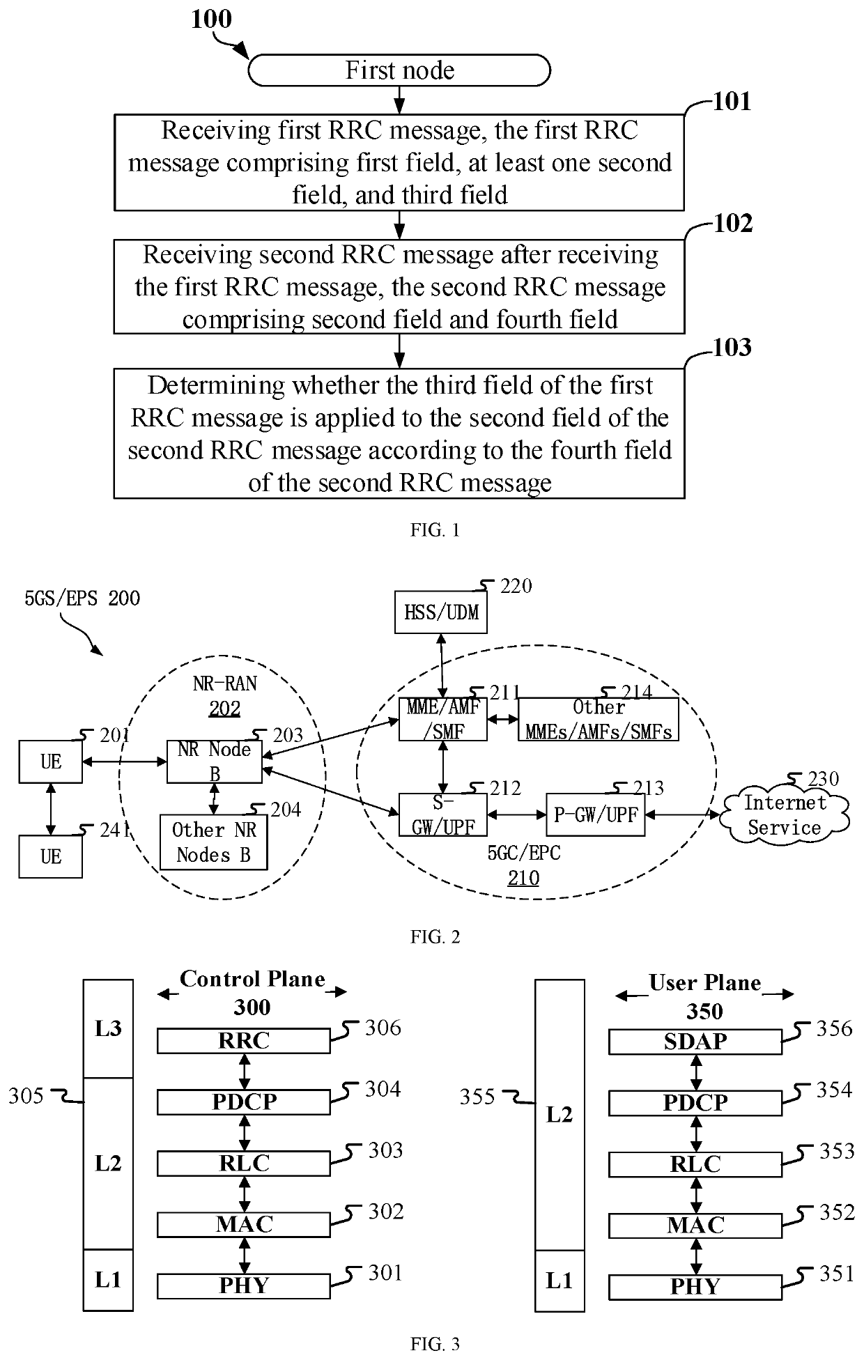
[0096]Embodiment 1 illustrates a schematic diagram of transmission of a first signaling according to one embodiment of the present disclosure, as shown in FIG. 1. In FIG. 1, each box represents a step. Particularly, the sequential order of steps in these boxes does not necessarily mean that the steps are chronologically arranged.
[0097]In embodiment 1, the first node in the present disclosure receives a first RRC message in step 101, and the first RRC message comprises a first field, at least one second field, and a third field; in step 102, receives a second RRC message after receiving the first RRC message, the second RRC message comprises a second field and a fourth field; and in step 103, determines whether the third field of the first RRC message is applied to the second field of the second RRC message according to the fourth field of the second RRC message;
[0098]herein, the second field comprises a logical channel ID; the first RRC message is used to configure a cell group, and...
embodiment 2
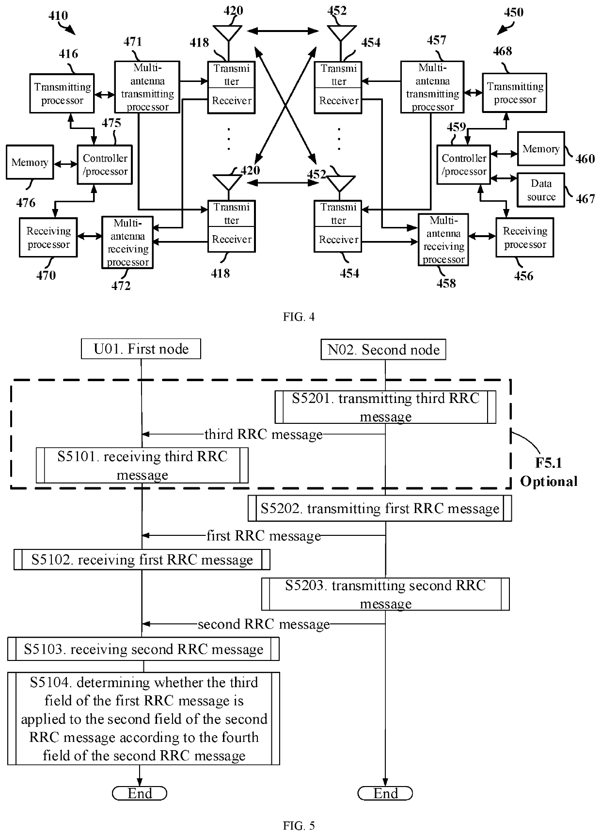
[0269]Embodiment 2 illustrates a schematic diagram of a network architecture according to one embodiment of the present disclosure, as shown in FIG. 2. FIG. 2 is a diagram illustrating a network architecture 200 of 5G NR, Long-Term Evolution (LIE) and Long-Term Evolution Advanced (LIE-A) systems. The 5G NR or LIE network architecture 200 may be called a 5G System (5GS) / Evolved Packet System (EPS) 200 or other appropriate terms. The 5GS / EPS 200 may comprise one or more UEs 201, an NG-RAN 202, a 5G Core Network / Evolved Packet Core (5GC / EPC) 210, a Home Subscriber Server (HSS) / Unified Data Management (UDM) 220 and an Internet Service 230. The 5GS / EPS 200 may be interconnected with other access networks. For simple description, the entities / interfaces are not shown. As shown in FIG. 2, the 5GS / EPS 200 provides packet switching services. Those skilled in the art will readily understand that various concepts presented throughout the present disclosure can be extended to networks providing...
embodiment 3
[0304]Embodiment 3 illustrates a schematic diagram of an example of a radio protocol architecture of a user plane and a control plane according to one embodiment of the present disclosure, as shown in FIG. 3. FIG. 3 is a schematic diagram illustrating an embodiment of a radio protocol architecture of a user plane 350 and a control plane 300. In FIG. 3, the radio protocol architecture for the control plane 300 is represented by three layers, which are a layer 1, a layer 2 and a layer 3, respectively. The layer 1 (L1) is the lowest layer and performs signal processing functions of various PHY layers. The L1 is called PHY 301 in the present disclosure. L2 305, above the PHY 301, comprises a Medium Access Control (MAC) sublayer 302, a Radio Link Control (RLC) sublayer 303 and a Packet Data Convergence Protocol (PDCP) sublayer 304. The PDCP sublayer 304 provides multiplexing among variable radio bearers and logical channels. The PDCP sublayer 304 provides security by encrypting a data pa...
PUM
 Abstract
Description
Claims
Application Information
 - R&D Engineer
- R&D Manager
- IP Professional
- Industry Leading Data Capabilities
- Powerful AI technology
- Patent DNA Extraction
Browse by: Latest US Patents, China's latest patents, Technical Efficacy Thesaurus, Application Domain, Technology Topic.
© 2024 PatSnap. All rights reserved.Legal|Privacy policy|Modern Slavery Act Transparency Statement|Sitemap