Aircraft lamp

a technology for aircraft and lamps, applied in semiconductor devices for light sources, light and heating equipment, transportation and packaging, etc., can solve the problems of unsecure driving state of light sources, and achieve the effect of improving the maintenance and good lighting state of lamps

Pending Publication Date: 2022-09-08
KOITO MFG CO LTD
View PDF11 Cites 0 Cited by
  • Summary
  • Abstract
  • Description
  • Claims
  • Application Information

AI Technical Summary

Benefits of technology

The present invention improves the maintainability of a lamp unit by allowing it to be detached from the lamp housing without needing to separate the housing or cover from the aircraft. This means that the lamp unit can be easily replaced or repaired without having to remove the entire lamp housing. It also ensures that the lamp unit is always in good condition, as it can be quickly replaced when needed.

Problems solved by technology

However, when a problem occurs in a part of the lamp unit, there is a concern that a good driving state of the light source may not be secured, and thus, it is necessary to improve the maintainability of the lamp unit.

Method used


Image

  • Aircraft lamp
  • Aircraft lamp
  • Aircraft lamp

Examples


first embodiment

Aircraft Lamp

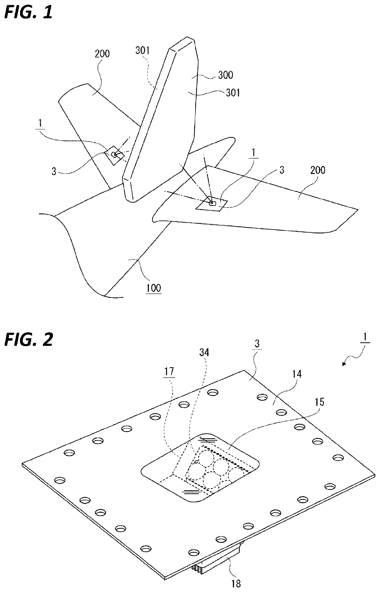
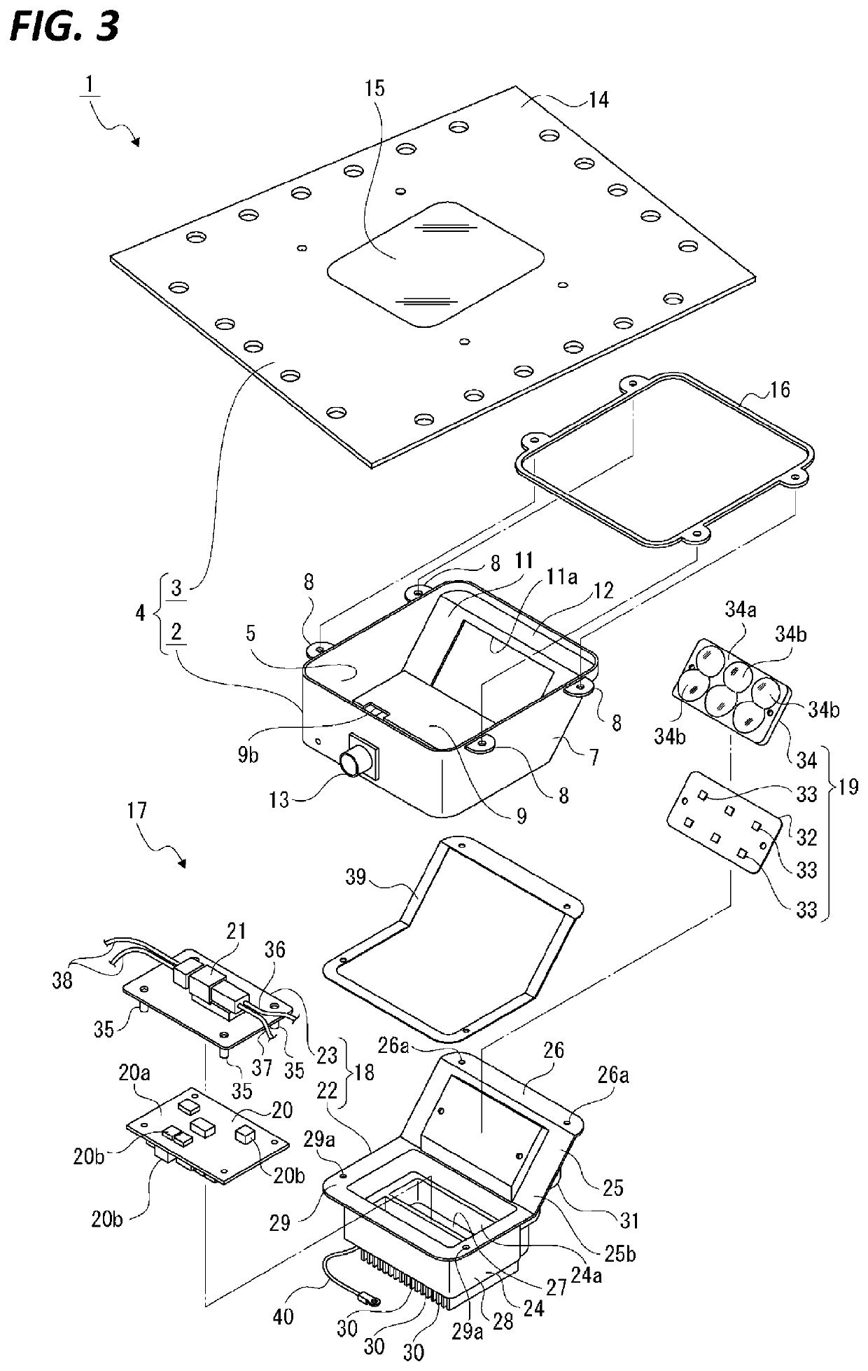
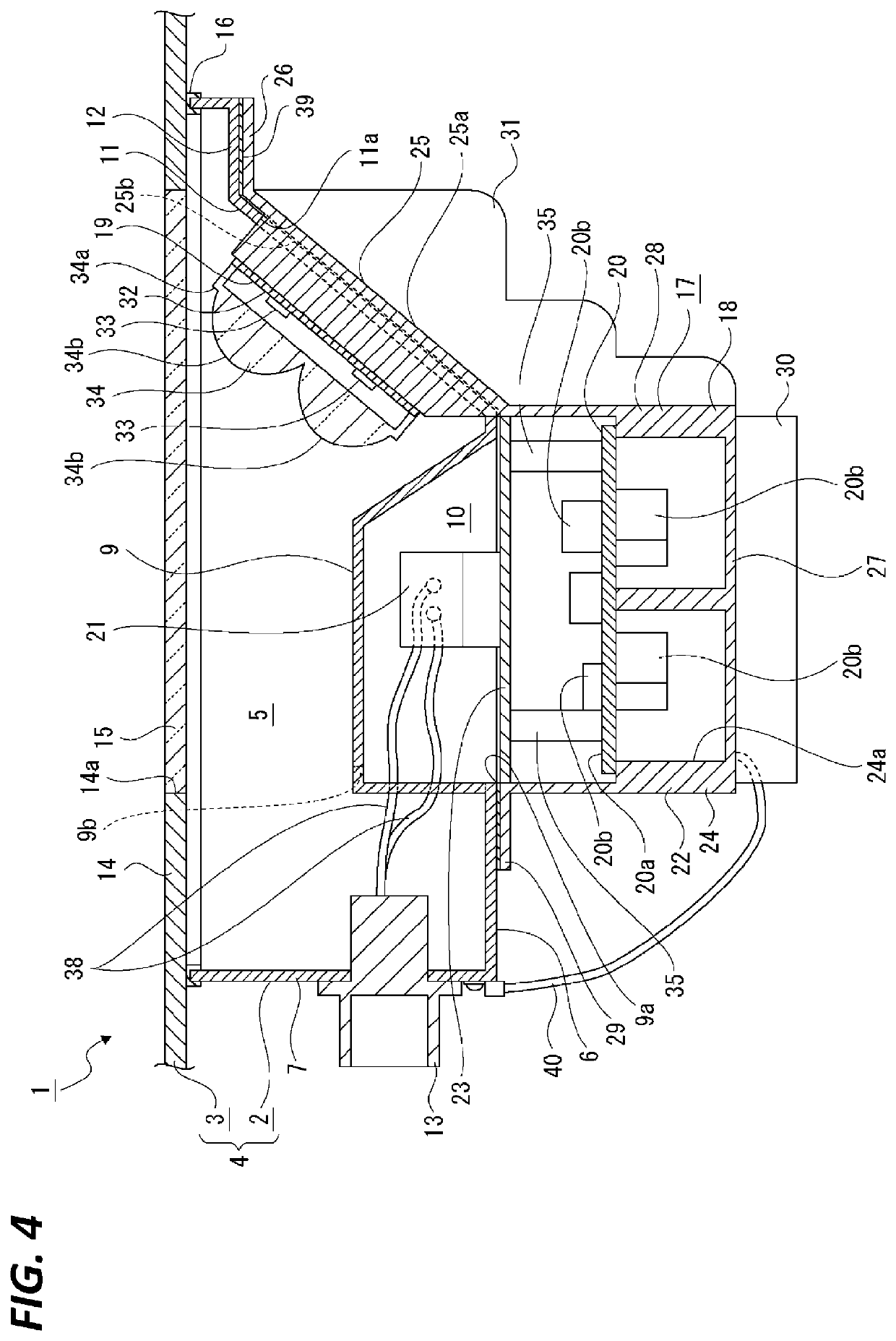
[0041]First, an aircraft lamp 1 according to a first embodiment will be described.

[0042]Hereinafter, descriptions will be made on an example in which the aircraft lamp 1 according to the present disclosure is applied to a logo lamp which is an external lighting and is attached to a horizontal tail wing. However, the scope of application of the present disclosure is not limited to the logo lamp, but may be applied to other external lighting used in an aircraft.

[0043]In the aircraft lamp 1, a lamp outer housing is configured by a lamp housing and a cover. In the following descriptions, front-rear, upward-downward, and left-right directions are illustrated by setting a coupling direction of the lamp housing and the cover to a vertical direction, the cover as an upper side, and the lamp housing as a lower side. Further, the aircraft lamp 1 is attached an upper surface side of the horizontal tail wing, and with respect to the left-right direction, the vertical tail wing side...

second embodiment

Aircraft Lamp

[0099]Subsequently, an aircraft lamp 51 according to a second embodiment will be described.

[0100]In the following, an example in which the aircraft lamp 51 according to the present disclosure is applied to an ice-inspection lamp which is an external lighting and is attached to an airframe is illustrated. However, the scope of application of the present disclosure is not limited to an ice-inspection lamp, but may be applied to other external lighting such as a logo lamp used in an aircraft.

[0101]The aircraft lamp 51 is attached to, for example, the left and right side surface portions of the airframe, and a lamp outer housing is configured by a lamp housing and a cover. In the following descriptions, front-rear, upward-downward, and left-right directions are illustrated by setting a coupling direction of the lamp housing and the cover to a left-right direction, the cover side as an outer side in the side direction, and the lamp housing side as an inner side in the side d...


PUM


Abstract

An aircraft lamp includes: a lamp outer housing configured by a lamp housing having an opening and a cover attached to the lamp housing in a state where the opening is closed, wherein an internal space is formed in the lamp housing as a first arrangement space; and a lamp unit that includes a light source module provided with a light source, an attaching base to which the light source module is attached, and a power receiving connector attached to the attaching base to supply power to the light source, wherein the lamp unit is configured to be detachable with respect to the lamp housing. The lamp housing includes an insertion hole communicating with the first arrangement space. The lamp housing is provided with an arrangement case portion having a second arrangement space opened on an outer surface side of the lamp housing.

Description

TECHNICAL FIELD[0001]The present disclosure relates to a technical field of an aircraft lamp used by being attached to, for example, an airframe of an aircraft.BACKGROUND[0002]There is an aircraft lamp including a lamp outer housing configured by a cover and a lamp housing, and a lamp unit that irradiates light emitted from a light source toward the outside (see, e.g., Patent Document 1 and Patent Document 2).[0003]There are various types of such aircraft lamps according to usage purposes, and as external lighting, for example, there is a collision prevention light that prevents collision between aircrafts, a flight light that indicates a flight posture or a flight direction of an airframe, a landing light that irradiates a runway during take-off and landing, and a logo lamp that illuminates a logo of an airline company drawn on an airframe.PRIOR ART DOCUMENTPatent Document[0004]Patent Document 1: Japanese Laid-Open Patent Publication No. 2010-033840[0005]Patent Document 2: Japanese...

Claims


Application Information

Patent Timeline
IPC IPC(8): B60Q1/00B64D47/06F21V23/06F21V29/503F21V29/76
CPCB60Q1/0094B64D47/06F21V23/06F21V29/503F21V29/76B64D2203/00F21Y2115/10B64D47/02
Inventor NAKAMURA, KAZUYOSHIYODA, TAKASHIISHIKIRIYAMA, MASARU
Owner KOITO MFG CO LTD
Why Eureka
Try Eureka