High resolution unambiguous radar

a radar and high-resolution technology, applied in the field of radar systems, can solve the problems of limiting the ability to have antennas external from the rf chip, affecting cost and complexity, and not being practicable on a single rf chip

Pending Publication Date: 2022-09-08
GM GLOBAL TECH OPERATIONS LLC
View PDF22 Cites 1 Cited by
  • Summary
  • Abstract
  • Description
  • Claims
  • Application Information

AI Technical Summary

Benefits of technology

[0003]Radar devices are generally useful in target detection and may commonly provide information indicating range / rate, azimuth and elevation of targets. Automotive radar devices, for example as used in forward looking target detection, are generally more concerned with azimuthal angular resolution and less concerned with elevational angular resolution. High resolution radar devices typically require large numbers of antennas with signal processing done on a radio frequency (RF) semiconductor chip (chip). The signal processing from such large numbers of antennas may not be practical on a single RF chip due to lengthy connecting traces between the antennas and the RF chip. Thus, multiple RF chips may be coupled to respective sub-sets of antennas. Antenna placement is critical to the ability of the radar system to estimate the angle of reflected radar signal arrival with high angular resolution and without angular ambiguity. Such antenna sub-sets may allow for flexibility of antenna placement with many degrees of freedom since the antennas are external to the RF chip and it is a relatively simple matter to provide for different individual antenna placements within each antenna sub-set and different placements of the various antenna sub-sets. Such radar systems may typically operate in millimeter range wavelength or about 7.5 millimeters (40 GHz) to about 1 millimeter (300 GHz). Automotive millimeter radar may operate from about 75 GHz to about 110 GHz and more particularly from about 77 GHz to about 81 GHz.
[0004]Improvements in angular resolution of radar devices are possible at higher operating frequency. It is known that higher angular resolution is proportional to operating frequency. Higher operating frequency may limit the ability to have antennas external from the RF chip. Radar devices operating at higher frequencies, for example at about 240 GHz, benefit from integrating antennas as part of the RF chip because at such high frequencies radar devices are very sensitive to the accurate position of antennas, gain loss is reduced with shorter connecting traces, crosstalk is reduced, and such integrations are robust to variations in temperature. However, each unique sub-set of antenna placements would require a unique RF chip manufacture thus negatively impacting cost and complexity. Thus, it becomes desirable to minimize the number of unique RF chips which undesirably constrains the degrees of freedom in antenna placements and negatively affects angular resolution and angular unambiguity.
[0005]Therefore, it is desirable to improve angular resolution and ambiguity performance of RF chip antenna integrated radar devices while also minimizing the number of unique RF chips required to do so.SUMMARY

Problems solved by technology

The signal processing from such large numbers of antennas may not be practical on a single RF chip due to lengthy connecting traces between the antennas and the RF chip.
Higher operating frequency may limit the ability to have antennas external from the RF chip.
However, each unique sub-set of antenna placements would require a unique RF chip manufacture thus negatively impacting cost and complexity.
Thus, it becomes desirable to minimize the number of unique RF chips which undesirably constrains the degrees of freedom in antenna placements and negatively affects angular resolution and angular unambiguity.

Method used


Image

  • High resolution unambiguous radar
  • High resolution unambiguous radar
  • High resolution unambiguous radar

Examples


Embodiment Construction

[0033]The following description is merely exemplary in nature and is not intended to limit the present disclosure, its application or uses. Throughout the drawings, corresponding reference numerals indicate like or corresponding parts and features.

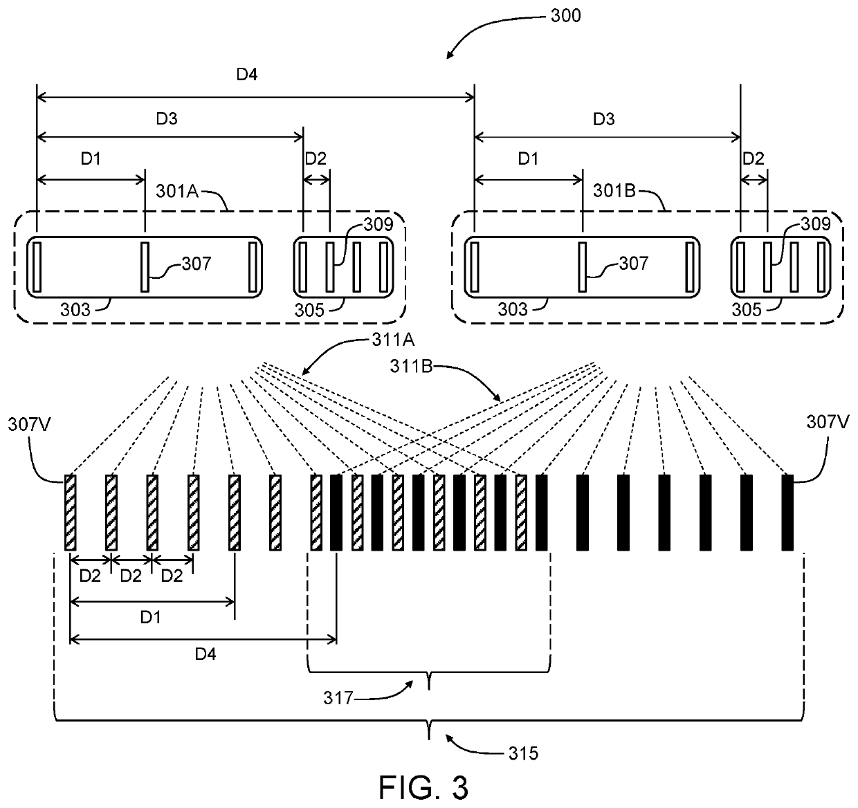
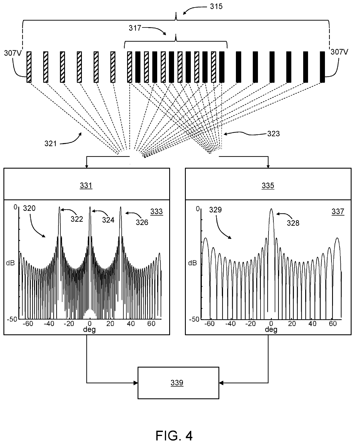
[0034]In accordance with one or more exemplary embodiments, methods and systems for high angular resolution and unambiguous angle estimation in a radar device are described herein. Exemplary embodiments may include minimal numbers of different RF chip antenna integrated radar devices. For example, at least two of a single type of RF chip antenna integrated packaging may be arranged to establish a virtual antenna array capable of high angular resolution and unambiguous angle estimation.

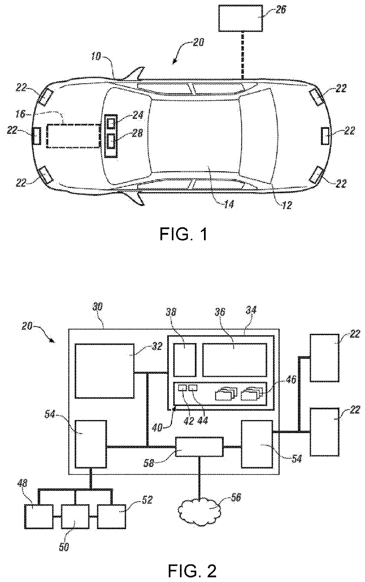
[0035]FIG. 1 shows an embodiment of a vehicle10, which includes a vehicle body 12 defining, at least in part, an occupant compartment 14. The vehicle 10, while shown in FIG. 1 as an automobile, may be any truck, aircraft, construction equipment, farm equipmen...


PUM


Abstract

A radar system and method include and employ a plurality of substantially identical transceiver sets establishing respective substantially identical, overlapping virtual antenna arrays. A first sub-array of widely spaced virtual antennas provides high angular resolution but high angular ambiguity. A second sub-array of narrowly spaced virtual antennas provides low angular ambiguity but low angular resolution.

Description

INTRODUCTION[0001]The subject disclosure relates to radar systems.[0002]Vehicles (e.g., automobiles, trucks, aircraft, construction equipment, farm equipment, factory equipment, whether user or autonomously operated) may be equipped with detection systems for monitoring surrounding environments. An example detection system may include radar devices that are used for detecting objects / obstacles, tracking objects, and avoiding obstacles. Radar devices may also be used in vehicles to alert a user (e.g., driver or passenger) and in advanced driver-assistance systems (ADAS).[0003]Radar devices are generally useful in target detection and may commonly provide information indicating range / rate, azimuth and elevation of targets. Automotive radar devices, for example as used in forward looking target detection, are generally more concerned with azimuthal angular resolution and less concerned with elevational angular resolution. High resolution radar devices typically require large numbers of...

Claims


Application Information

Patent Timeline
Patent Type & Authority Applications(United States)
IPC IPC(8): G01S7/03G01S13/42
CPCG01S7/032G01S13/426G01S13/931G01S7/282G01S7/285G01S13/42G01S2013/93272G01S2013/93271
Inventor BIALER, ODEDJONAS, AMNON
Owner GM GLOBAL TECH OPERATIONS LLC
Why Eureka
Try Eureka