Eureka AIR delivers breakthrough ideas for toughest innovation challenges, trusted by R&D personnel around the world.

Integrated electronic brake system and control method thereof

Pending Publication Date: 2022-09-15
HYUNDAI MOBIS CO LTD
View PDF0 Cites 0 Cited by
  • Summary
  • Abstract
  • Description
  • Claims
  • Application Information

AI Technical Summary

Benefits of technology

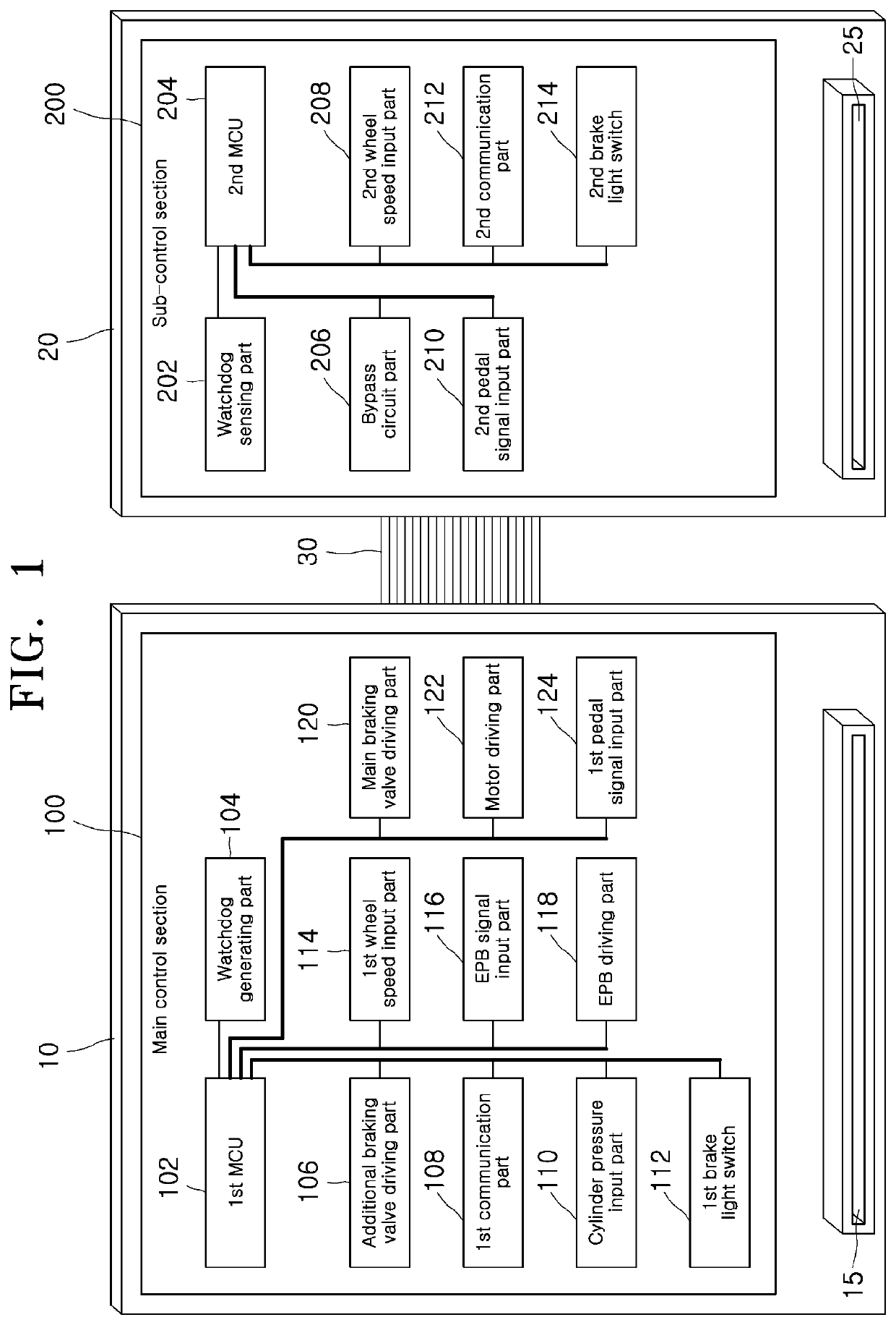
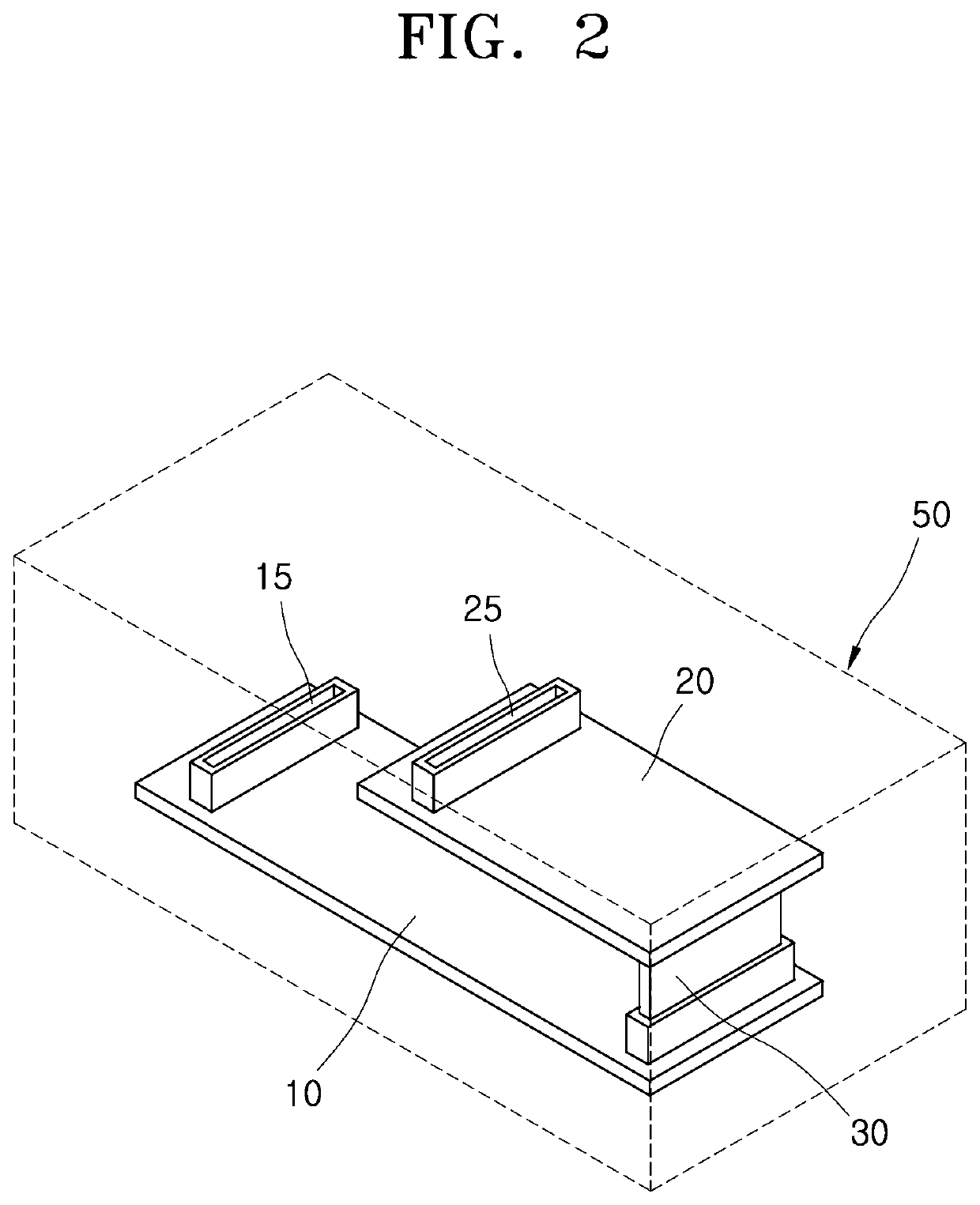
The integrated electronic brake system and control method described in this patent make use of two main control sections and one sub-control section that are all connected within a single box. This arrangement means that if the main control section fails, the main braking valve and braking motor can still be controlled through the sub-control section, reducing the size and weight of the brake system and improving stability in the case of a small autonomous vehicle.

Problems solved by technology

Therefore, for the safety of passengers, it cannot be too much to emphasize the stability of the brake system.
In order to implement a brake apparatus by combining the electronically controlled brake systems as described above, there is a problem in that a large number of wires are required to operate the respective brake systems.
Further, in order to install the respective electronically controlled braking systems, mounting positions for mounting the respective systems are required, so there is a problem in securing a space in a vehicle.
On the other hand, if a failure occurs in a vehicle during driving, so the electronically controlled brake systems become inoperative, it may lead to a serious accident, so it is necessary to prepare for the inoperative state of the electronically controlled brake systems.

Method used


Image

  • Integrated electronic brake system and control method thereof
  • Integrated electronic brake system and control method thereof
  • Integrated electronic brake system and control method thereof

Examples


Embodiment Construction

[0032]As is traditional in the corresponding field, some exemplary embodiments may be illustrated in the drawings in terms of functional blocks, units, and / or modules. Those of ordinary skill in the art will appreciate that these block, units, and / or modules are physically implemented by electronic (or optical) circuits such as logic circuits, discrete components, processors, hard-wired circuits, memory elements, wiring connections, and the like. When the blocks, units, and / or modules are implemented by processors or similar hardware, they may be programmed and controlled using software (e.g., code) to perform various functions discussed herein. Alternatively, each block, unit, and / or module may be implemented by dedicated hardware or as a combination of dedicated hardware to perform some functions and a processor (e.g., one or more programmed processors and associated circuitry) to perform other functions. Each block, unit, and / or module of some exemplary embodiments may be physica...


PUM


Abstract

An integrated electronic brake system includes a main control section configured in a first area to receive one or more of a value from a pedal sensor, a value from a cylinder pressure sensor, a value from a wheel speed sensor, or an EPB signal to perform EPB control and drive a main braking valve and a braking motor for the main braking of a vehicle, and to drive an additional braking valve for the additional braking, a sub-control section configured in a second area to receive one or more of the value from the pedal sensor, the value from the wheel speed sensor, or the EPB signal to perform the EPB control and drive the main braking valve and the braking motor through a bypass circuit, and a connection bus connecting the first area and the second area mounted in one box to transfer signals between the main control section and the sub-control section.

Description

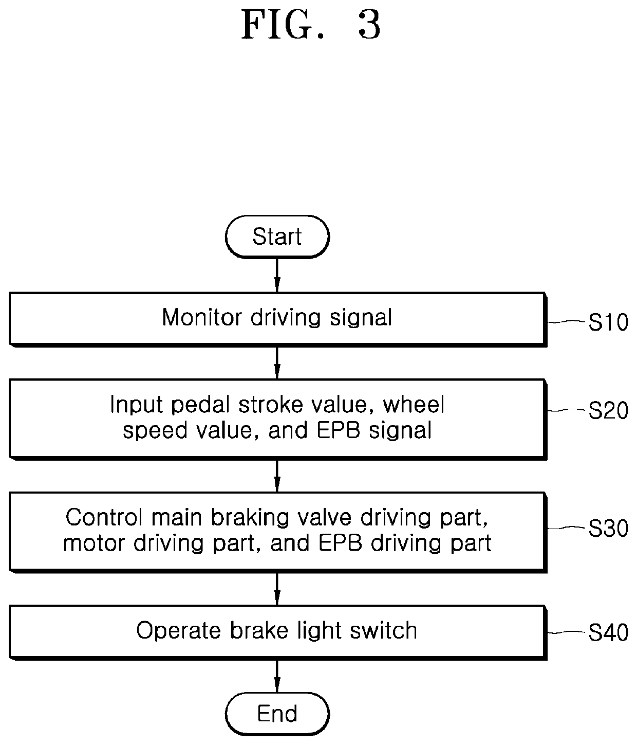
CROSS-REFERENCE TO RELATED APPLICATION[0001]This application claims priority from and the benefit of Korean Patent Application No. 10-2021-0032932, filed on Mar. 12, 2021, which is hereby incorporated by reference for all purposes as if set forth herein.BACKGROUNDField[0002]Exemplary embodiments of the present disclosure relate to an integrated electronic brake system and a control method thereof, and more particularly, to an integrated electronic brake system in which a control module thereof is configured into a main control section and a sub-control section, which are connected via an internal connection bus, in two independent areas, respectively, in a single box such that in the event of a failure of the main control section, a main braking valve and a braking motor can be controlled through the sub-control section, and a control method thereof.Discussion of the Background[0003]A brake system is absolutely necessary for a vehicle. This is because a vehicle that cannot be stoppe...

Claims


Application Information

Patent Timeline
IPC IPC(8): B60T8/88B60T17/22B60T8/94B60Q1/44
CPCB60T8/885B60T17/22B60T8/94B60Q1/441B60T2220/04B60T2270/88B60T2240/00B60T2270/82B60T2270/402B60T2270/404B60T2270/406B60T2270/10B60T2270/30B60T2270/413B60T8/172B60T7/042B60T13/662B60T13/686B60T8/329B60T17/221B60T13/745B60T8/171B60T8/4086B60R16/023B60Y2400/306B60Y2400/3032
Inventor LEEPARK, JAE HYUNJEON, IN SOOKIM, BO MIN
Owner HYUNDAI MOBIS CO LTD
Why Eureka
Eureka Blog
Learn More