Laser metal deposition system

a metal deposition system and laser technology, applied in additive manufacturing, manufacturing tools, coatings, etc., can solve the problems of significant temperature rise likely to impact the components of the deposition system, deformation of the feed nozzle of the wire, and the feed nozzle (generally made of copper) tends to lengthen under the effect of hea

Pending Publication Date: 2022-09-15
SN DETUDE & DE CONSTR DE MOTEURS DAVIATION S N E C M A
View PDF0 Cites 0 Cited by
  • Summary
  • Abstract
  • Description
  • Claims
  • Application Information

AI Technical Summary

Benefits of technology

[0014]Thus, this solution allows to achieve the above-mentioned objective. In particular, the cooling of the feed nozzle allows t

Problems solved by technology

Thus, in the case of a long deposit, the energy brought to the wire to melt it can lead to a significant temperature rise likely to impact the components of the deposition system.
In particular, the high temperature of the molten metal can cause a deformation of the feed nozzle of the wire located nearby.
Indeed, this feed nozzle (generally made of copper) tends to lengthen under the effect

Method used


Image

  • Laser metal deposition system
  • Laser metal deposition system
  • Laser metal deposition system

Examples


Embodiment Construction

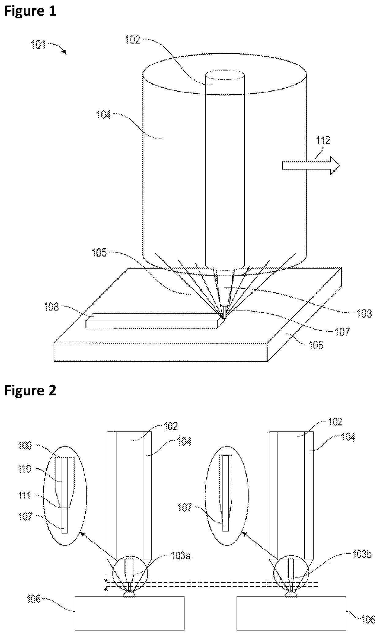
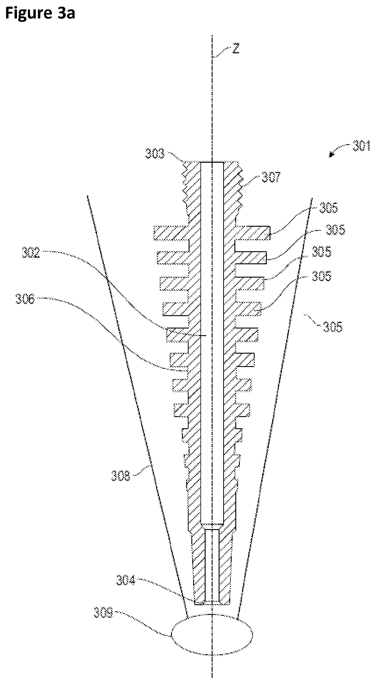
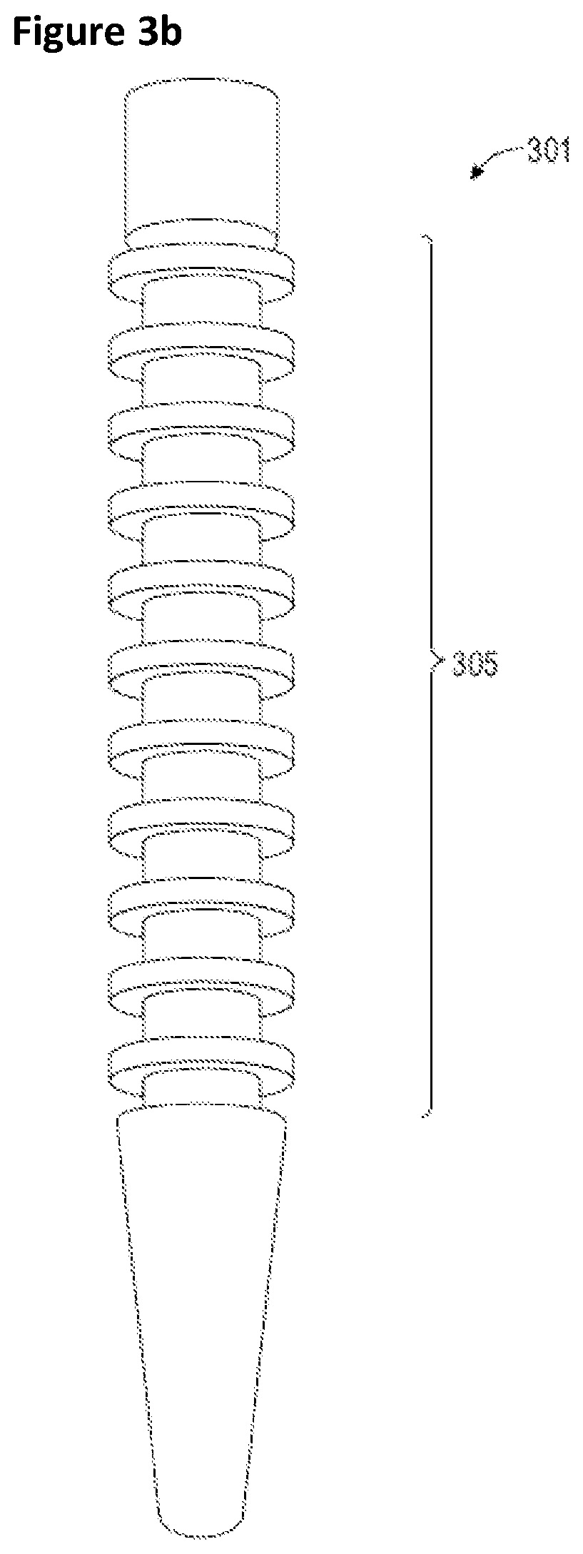
[0031]With reference to FIG. 3a and FIG. 3b, an embodiment of a feed nozzle of a laser metal deposition system according to the invention will now be described. The person skilled in the art will appreciate that, with the exception of the feed nozzle, all the other components of such a system conform to those of a system of the prior art such as that described with reference to FIGS. 1 and 2. In particular, in addition to the feed nozzle, the laser metal deposition system with which it is integrated comprises a delivery system adapted to supply a metal wire to the inlet orifice of the feed nozzle and a laser head adapted to generate the melting of the metal at the level of the outlet orifice of the feed nozzle.

[0032]In the illustrated example, the feed nozzle 301 comprises a tubular wall 306 that defines a cylindrical conduit 302 that passes through the nozzle along the longitudinal axis Z. The conduit extends from the inlet orifice 303 to the outlet orifice 304. The role of the con...


PUM

PropertyMeasurementUnit
Thicknessaaaaaaaaaa
Thicknessaaaaaaaaaa
Diameteraaaaaaaaaa

Abstract

The invention relates to a laser metal deposition system, which comprises a feed nozzle (301), the tubular wall (306) of which has external fins (305) designed to allow heat dissipation by heat exchange with the immediate surroundings of the feed nozzle (301).

Description

TECHNICAL FIELD OF THE INVENTION[0001]The invention relates to the field of the additive manufacturing of metal parts, in particular for aircrafts. In particular, the invention relates to a laser metal deposition system. The invention also relates to an additive manufacturing method implementing the laser metal deposition system.BACKGROUND[0002]The prior art comprises in particular the documents GB-A-2 558 897, JP-A-2005 169396, U.S. Pat. No. 4,560,858 and CN-U-202 367 348.[0003]The Direct Metal Deposition (DMD) is an additive manufacturing technique that allows the production of complex parts by depositing and stacking successive layers of a specific material. Among the many variations of this technique is the technique referred to as laser metal deposition (LMD) technique. To carry out a deposition, this technique implies regularly feeding a liquid bath of molten metal, located on the surface of a substrate, on which the deposition takes place. In particular, metal is brought to t...

Claims


Application Information

Patent Timeline
IPC IPC(8): C23C24/10B33Y10/00B33Y30/00
CPCC23C24/106B33Y10/00B33Y30/00B22F12/20B22F12/53B22F10/25B33Y40/00B23K26/0006B23K26/1476B23K26/14B23K26/34B23K26/703Y02P10/25
Inventor POUZET, SEBASTIEN YOHANNSEINCE, HERVE ANTOINE FREDERICGRALL, TERENCEMAUVOISIN, RONAN
Owner SN DETUDE & DE CONSTR DE MOTEURS DAVIATION S N E C M A
Why Eureka
Try Eureka