
Exhaust device of engine and work machine

a technology of work machine, which is applied in the direction of sound producing device, machine/engine, instruments, etc., can solve the problem that the exhaust sound of the left and right exhaust gas inlet pipe cannot be reduced in a well-balanced manner

Active Publication Date: 2022-09-15
HONDA MOTOR CO LTD
View PDF5 Cites 0 Cited by
  • Summary
  • Abstract
  • Description
  • Claims
  • Application Information

AI Technical Summary

Benefits of technology

The present invention is an exhaust device that reduces exhaust sound from a vehicle's engine. It achieves this by using a muffler that contains a catalyst. This helps to create a balanced and effective reduction of exhaust sound from the vehicle.

Problems solved by technology

Accordingly, the exhaust sound of the exhaust gas from the left and right exhaust gas inlet pipes may not be reduced in a well-balanced manner.

Method used


Image

  • Exhaust device of engine and work machine
  • Exhaust device of engine and work machine
  • Exhaust device of engine and work machine

Examples


Embodiment Construction

1>

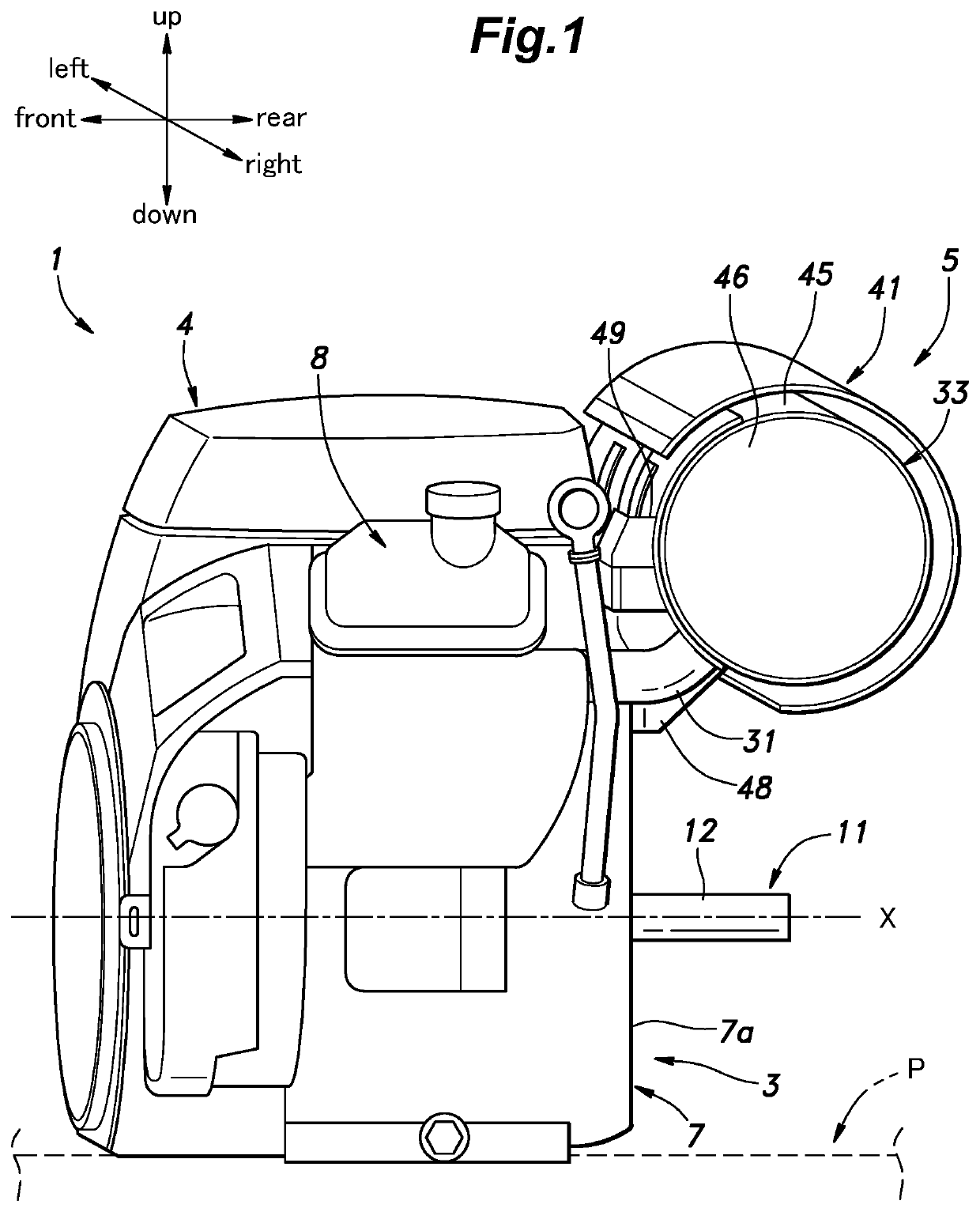
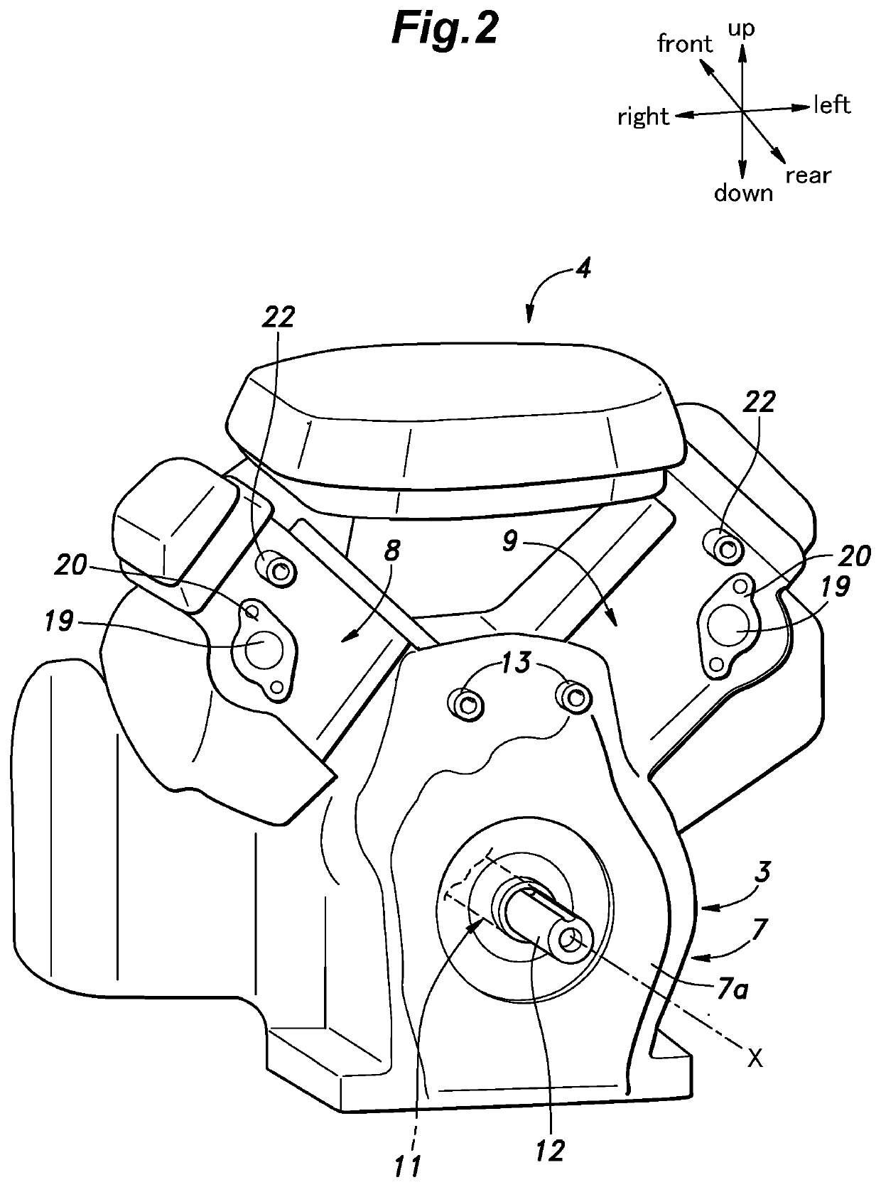
[0039]In the following, a V-type engine 1 (hereinafter abbreviated as “engine 1”) as an internal combustion engine according to an embodiment of the present invention will be described with reference to FIGS. 1 to 5. Hereinafter, for convenience of explanation, a left side in FIG. 1 is defined as a front side of the engine 1. Further, in this specification, when an expression like “fixed by bolt(s) (not shown)” is used, a member may be fixed by normal bolt(s) having a screw on only one side or by stud bolt(s) having screws on both sides.

[0040]With reference to FIG. 1, the engine 1 consists of a general-purpose engine used as a power source of a work machine P. For example, the work machine P consists of a cutting machine such as a concrete cutter, a floor treatment machine such as a floor leveler, a high-pressure washer, a generator, or the like. The engine 1 consists of an OHV air-cooled engine including two cylinders. In another embodiment, the engine 1 may consist of an engine ...


PUM


Abstract

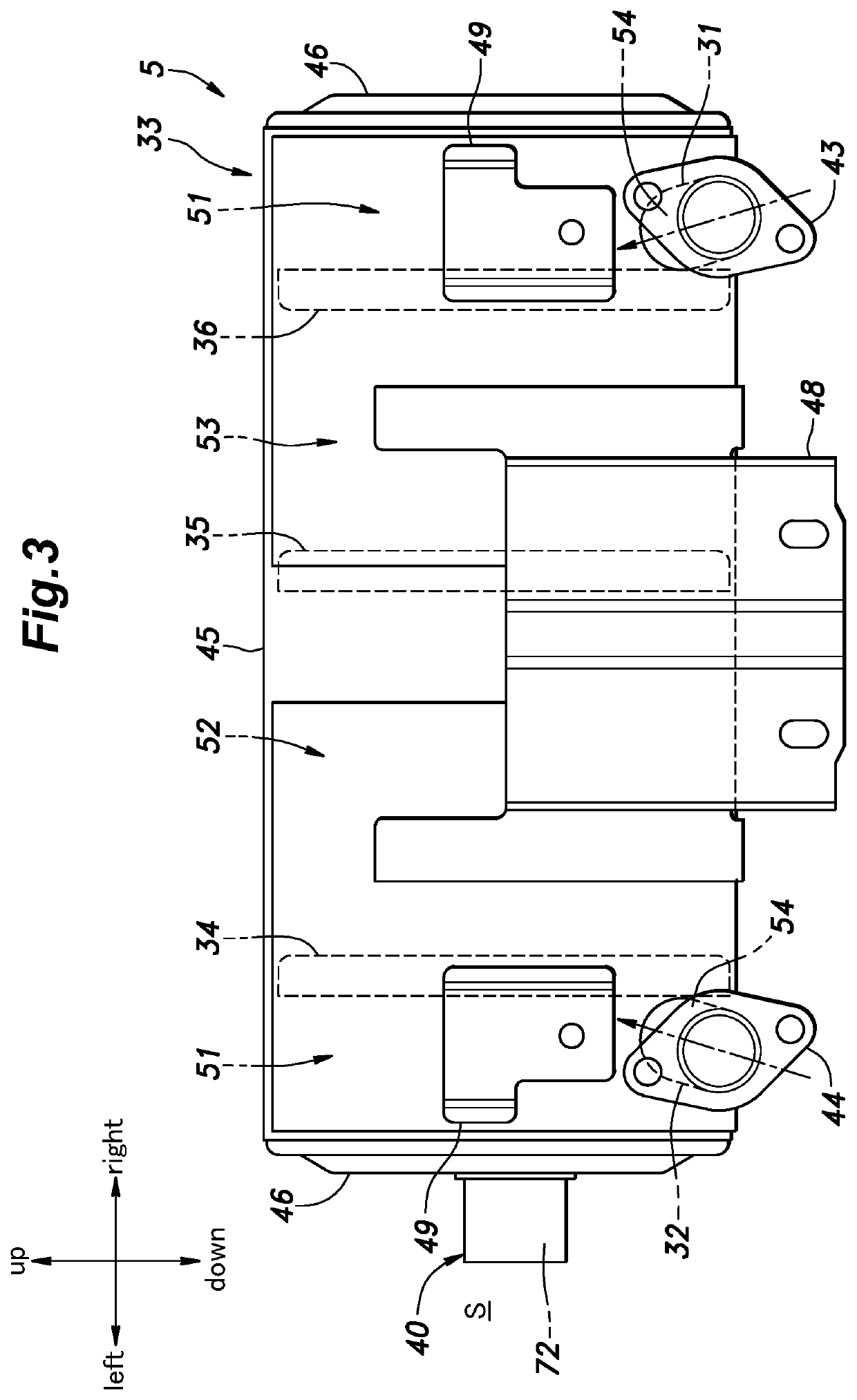
An exhaust device of an engine includes: a muffler provided with a plurality of muffling chambers separated by a plurality of partition walls, a communication pipe accommodated in the muffler and penetrating at least one of the partition walls, and a catalyst accommodated in the muffler and penetrating at least one of the partition walls, wherein the muffling chambers include: a pair of first muffling chambers each provided with an inlet port for exhaust gas; a second muffling chamber communicating with the pair of first muffling chambers via the communication pipe; and a third muffling chamber communicating with the second muffling chamber via the catalyst.

Description

TECHNICAL FIELD[0001]The present invention relates to an exhaust device of an engine and a work machine.BACKGROUND ART[0002]Conventionally, an engine is provided with an exhaust device for discharging exhaust gas generated in a combustion process. The exhaust device includes an exhaust pipe through which the exhaust gas passes, a catalyst configured to purify the exhaust gas, a muffler configured to reduce an exhaust sound, and the like.[0003]For example, JP2007-92663A discloses an exhaust muffler accommodating a catalytic converter. This exhaust muffler includes a first expansion chamber, a second expansion chamber communicating with the first expansion chamber via a first communication pipe, a third expansion chamber communicating with the second expansion chamber via the catalytic converter, and a fourth expansion chamber communicating with the third expansion chamber via a second communication pipe.[0004]In the exhaust muffler disclosed in JP2007-92663A, the exhaust gas from a r...

Claims


Application Information

Patent Timeline
Patent Type & Authority Applications(United States)
IPC IPC(8): F01N3/28F01N1/02G10K11/16
CPCF01N3/2885F01N1/02G10K11/161F01N3/00F01N3/0211F01N3/24
Inventor YASOSHINA, SAYAKAMURAO, ATSUSHI
Owner HONDA MOTOR CO LTD
Learn More