
engine driven work machine

An engine-driven, working machine technology, applied in the direction of engine components, machines/engines, mechanical equipment, etc., can solve problems such as difficult water vapor intake into the steam intake port, difficulty in ensuring the amount of distilled water generated, and difficulty in ensuring the amount of water vapor condensation , to achieve excellent heat insulation, light weight and low cost

Active Publication Date: 2016-04-27
HONDA MOTOR CO LTD
View PDF6 Cites 0 Cited by
  • Summary
  • Abstract
  • Description
  • Claims
  • Application Information

AI Technical Summary

Problems solved by technology

Therefore, the above-mentioned steam inlet of the communication pipe is formed small, and it is difficult to efficiently take in the water vapor evaporated in the evaporation region into the steam inlet.
Therefore, it is difficult to ensure the amount of condensation of water vapor evaporated by the waste heat of the engine, and it is difficult to ensure a sufficient amount of distilled water.

Method used


Image

  • engine driven work machine
  • engine driven work machine
  • engine driven work machine

Examples


Embodiment Construction

[0075] Hereinafter, when describing the examples, in the drawings, "Fr", "Rr", "L" and "R" represent the front, rear, left and right sides.

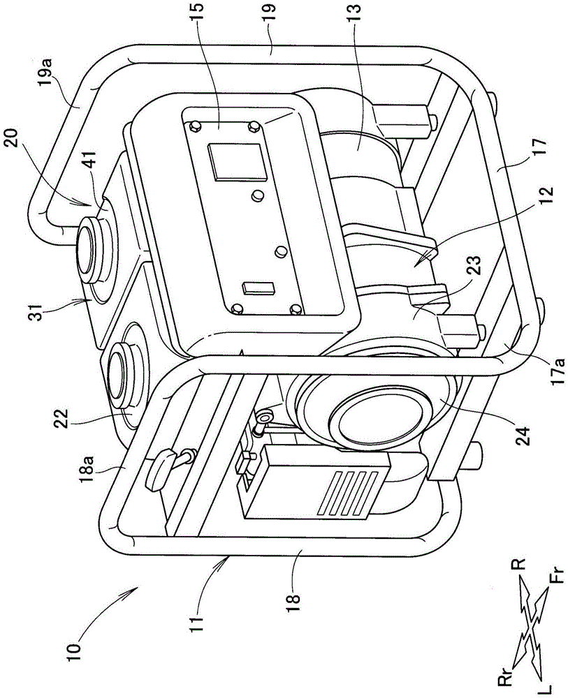
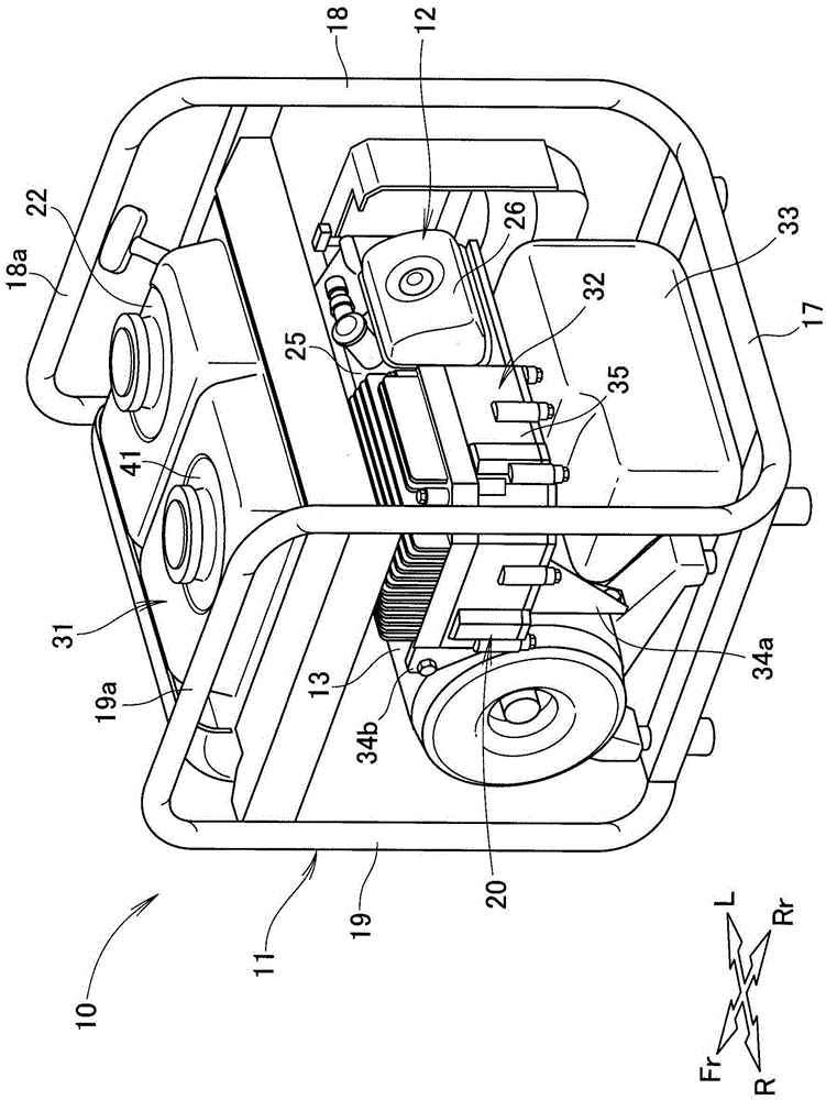
[0076] like figure 1 , figure 2 As shown, the engine-driven working machine 10 is provided with: a frame 11, which forms the outer frame of the engine-driven working machine 10; an engine 12, which is arranged at the front left lower part of the frame 11; generating device 20 disposed adjacent to generator 13 and engine 12 ; and operation panel 15 disposed in front of fuel tank 22 of engine 12 and raw water tank 41 of water generating device 20 .

[0077] The frame 11 has: a base 17 that supports the engine 12, the generator 13, and the clean water tank 33 of the water generator 20; a left frame 18 that is bent upward from the left end of the base 17; and a right frame 19 that It is bent upward from the right end of the base 17 . The engine-driven work machine 10 can be transported by holding the grip portion 18a of the left frame 18...


PUM


Abstract

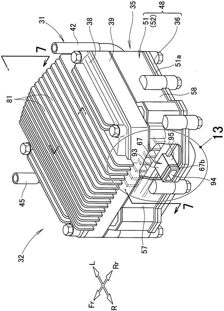
An engine-driven operation machine is provided. The engine-driven operation machine (10) is provided with a water generation device (20). The water generation device (20) allows raw water (29) to evaporate by utilization of waste heat of an engine (12), and allows water vapor evaporated to condense to generate purified water (69). The water generation device (20) is provided with an evaporator (35). The evaporator (35) allows the raw water (29) to evaporate by utilization of waste heat of waste gas guided by a heating part (53). The evaporator (35) is provided with: a gas taking part (66) for taking waste gas from a gas discharging pipe (27); and a gas discharging part (67) for discharging the waste gas into the gas taking part (66) to the outside (68) of the evaporator (35). A heating main body (65) is inclined to form a downward slope from towards the gas taking part (66) to the gas discharging part (67).

Description

technical field [0001] The present invention relates to an engine-driven working machine provided with a water generating device for evaporating raw water by using waste heat of an engine, and condensing the evaporated water vapor to generate purified water. Background technique [0002] For example, as disclosed in Japanese Patent Application Laid-Open No. 2012-24699, there is known an engine-driven working machine that takes water (raw water) from a river or the like into a water pump, diverts a part of the taken-in raw water, and utilizes The residual heat of the engine evaporates the diverted raw water, and uses the diverted raw water to condense the evaporated steam to generate clean water. [0003] According to this engine-driven work machine, when the water pump is driven, a part of the raw water taken into the water pump is guided to the raw water distribution pipe, and the guided raw water is introduced into the exhaust pipe of the engine through the raw water distr...

Claims


Application Information

Patent Timeline
Patent Type & Authority Patents(China)
IPC IPC(8): C02F1/16
CPCC02F1/16F01N5/02F02B63/06F02B65/00
Inventor 冈部格
Owner HONDA MOTOR CO LTD
Learn More