Back light module and liquid crystal display thereof

a back light module and liquid crystal display technology, applied in the field of back light modules and lcds, can solve the problems of high cost, difficulty in assembling, difficulty in locking and attaching tasks, etc., and achieve the effects of low cost, low cost, and resistance to lgp melting

Active Publication Date: 2012-09-20
TCL CHINA STAR OPTOELECTRONICS TECH CO LTD
View PDF1 Cites 23 Cited by
  • Summary
  • Abstract
  • Description
  • Claims
  • Application Information

AI Technical Summary

Benefits of technology

[0005]The main purpose of this invention lies in providing a back light module with convenient assembly, low cost, and the resistance of the LGP melting by the LED; this invention also provides an LED comprising the back light module.
[0025]Compared with the prior art, this invention provides the back light module and the LED thereof, and adopts the elastic clamping fastener to fasten the PCB and the rear panel. At the same time, since the elastic clamping fastener is higher than the LED surface, the LGP firstly contacts the top of the elastic clamping fastener and the top supports the LGP when the LGP deforms due to reasons such as thermal expansion or assembling allowance etc., which avoids that the LGP is melted when touching the high-temperature surface of the LED. With low cost, the back light module of this invention is easily assembled and can prevent the LGP from melting.

Problems solved by technology

However, the PCB is generally narrow and the adopted screw is relatively small, and thereby causing difficulties on locking and attaching task.
Therefore, the technical problems including assembling difficulty, high cost, and easily melting of the LGP exist in the back light module of the prior art.

Method used


Image

  • Back light module and liquid crystal display thereof
  • Back light module and liquid crystal display thereof
  • Back light module and liquid crystal display thereof

Examples


first embodiment

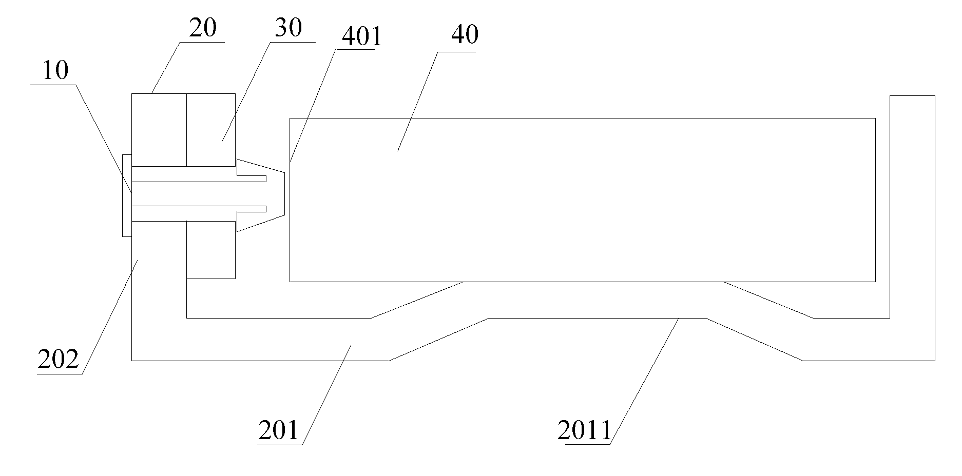
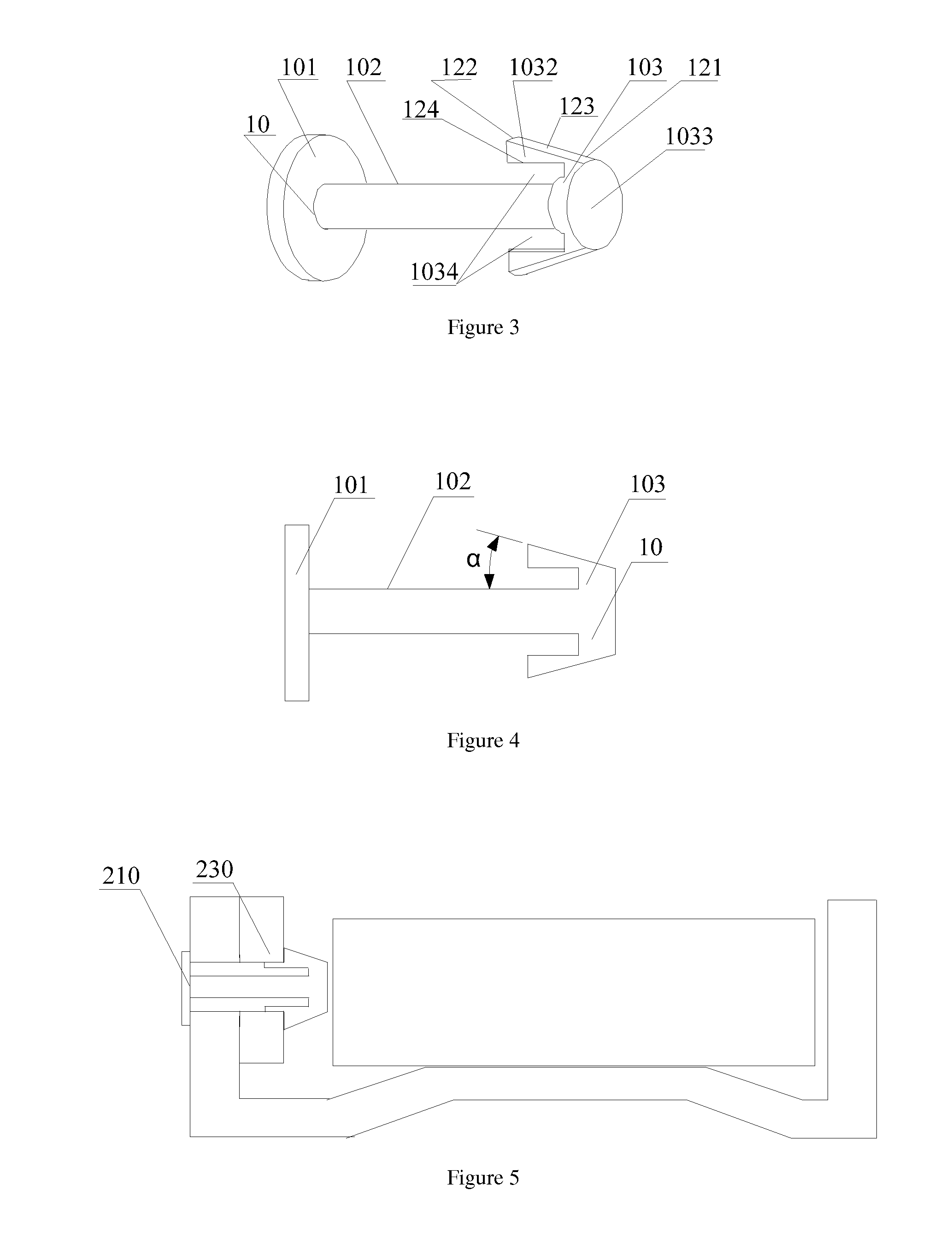
[0040]Specifically, please refer to FIG. 3 and FIG. 4 together. The elastic clamping fastener 10 of the first embodiment includes a base plate 101, a fastener 103, and a long rod 102 connecting the base plate 101 and the fastener 103. The base plate 101 is positioned on an outside surface of the sidewall 202 of the rear panel 20; the long rod 102 is positioned in the first through-hole of the sidewall 202 and the second through-hole of the PCB 30; the fastener 103 is positioned on the surface of the PCB 30. The long rod 102 is a cylinder with the semi diameter less than the first through-hole and the second through-hole.

[0041]The fastener 103 includes a top 1033 and two elastic wedge-shaped protuberances 1032. The top 1033 is approximately a circular disk shape. The surface (not labeled) of the top 1033 is a flat surface parallel to the light input surface 401 of the LGP 40, and higher than the surface of the LED 50 to press the LGP 40 while the LGP is expanding, which will not dama...

third embodiment

[0048]The back light module of this invention is not limited to the above embodiments. For example, the elastic clamping fastener of every embodiment can be applied in the back light module of the third embodiment; in the above embodiments, the base plate 101 can be round as well as quadrate, rectangular and polylateral, etc.

[0049]In the above embodiments, the number of the elastic wedge-shaped protuberances 1032, 2032, 3032 and 4032 can be one or more than 3. The long rod 102 of the elastic clamping fastener 10 of the first embodiment can also be cuboids, etc., correspondingly, the first through-hole of the sidewall 202 of the rear panel 20 and the second through-hole of the PCB 30 can also be rectangular, etc.

[0050]Furthermore, this invention also puts forward one kind of the liquid crystal display, which includes a liquid crystal panel and the back light module of the above embodiments. Here, we will not go further on them.


PUM

PropertyMeasurementUnit
elasticaaaaaaaaaa
diametersaaaaaaaaaa
diameteraaaaaaaaaa

Abstract

This invention relates to a back light module and a liquid crystal display thereof. The back light module includes a rear panel, an LGP, a PCB, a plurality of LEDs and at least an elastic clamping fastener. The rear panel includes a base plate and at least a sidewall. The LGP is positioned on the base plate. The PCB opposite to the LGP is positioned on the sidewall of the rear panel. The LEDs are positioned on the PCB. At least an elastic clamping fastener successively passes through the rear panel and the PCB to fasten the rear panel and the PCB. In addition, the top of the elastic clamping fastener is higher than the surface of the LEDs. The back light module and the liquid crystal display thereof in this invention are simple in structure, convenient in assembly, and low in cost.

Description

FIELD OF THE INVENTION[0001]This invention relates to a back light module and an LCD thereof, in particular to a side-light type back light module and an LCD comprising the side-light type back light module.BACKGROUND OF THE INVENTION[0002]The existing back light module usually includes a light guide plate (LGP), a rear panel, a PCB (Printed Circuit Board), and a plurality of LEDs (Light Emitting Diodes) fixed on the PCB. Generally, there are two following kinds of fixed modes of the PCB: a, a heat conductive adhesive tape is pasted between the PCB and the rear panel; b, a screw is used to lock and attach the PCB and the rear panel. Wherein, the advantage of mode a is that the heat conductive adhesive tape can fill in the gap between the two interfaces, but the cost of the heat conductive adhesive tape is high. The mode b can reach the close contact of the two interfaces. The cost of the screw is lower than that of the heat conductive adhesive tape. However, the PCB is generally nar...

Claims


Application Information

Patent Timeline
Patent Type & Authority Applications(United States)
IPC IPC(8): G02F1/1335G09F13/04
CPCF21S8/00F21V17/16G02F1/1335G02F1/133615G02B6/009G02F2001/133612G02F2201/465G02B6/0088G09F13/04G02F1/133612
Inventor TANG, GUOFU
Owner TCL CHINA STAR OPTOELECTRONICS TECH CO LTD
Why Eureka
Try Eureka