Waste gas purifying system and waste gas purifying method

An exhaust gas purification system and oxidation catalyst technology, applied in chemical instruments and methods, charging systems, separation methods, etc., can solve the problems of filter melting, incomplete regeneration, and the inability to control the filter temperature at the optimal temperature, etc., to achieve The effect of preventing melting

Inactive Publication Date: 2004-09-29
MITSUBISHI FUSO TRUCK AND BUS CORPORATION
View PDF0 Cites 23 Cited by
  • Summary
  • Abstract
  • Description
  • Claims
  • Application Information

AI Technical Summary

Problems solved by technology

It is the second additional fuel amount that has a great influence on the temperature of the filter, but according to the technology disclosed in the above patent document, since the second additional fuel amount is set constant, it is impossible to control the temperature of the filter
If the filter temperature is too high, PM burns in a short time and the filter temperature becomes higher, which in turn may cause melting of the filter, while too low temperature will cause incomplete regeneration
[0010] The amount of additional fuel injection can be effectively controlled according to engine speed and engine load, but even this method cannot control the temperature of the filter at the optimum temperature

Method used


Image

  • Waste gas purifying system and waste gas purifying method
  • Waste gas purifying system and waste gas purifying method
  • Waste gas purifying system and waste gas purifying method

Examples


Embodiment Construction

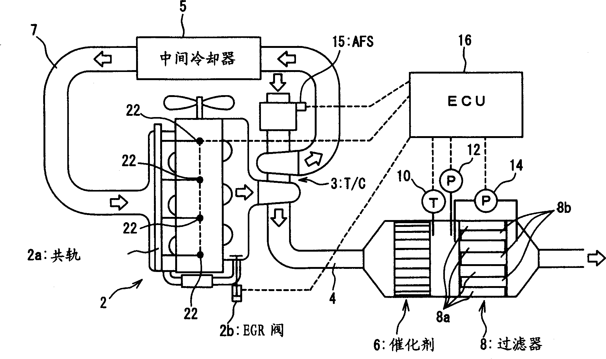
[0040] The exhaust gas purification system according to the embodiment of the present invention will be described below with reference to the accompanying drawings, wherein figure 1 It is a schematic diagram of the overall structure of the exhaust gas purification system. In this embodiment, the engine 2 is a diesel engine using diesel (HC) as fuel. The engine 2 is equipped with a common rail type fuel injection system in which fuel is stored in a high-pressure accumulator (common rail) 2a shared by a plurality of cylinders before being injected.

[0041] In the exhaust passage 4 of the engine 2, an oxidation catalyst (hereinafter simply referred to as "catalyst") 6 and a diesel particulate filter (hereinafter simply referred to as "filter") 8 are disposed in order from the upstream end of the exhaust gas flow. Furthermore, the turbocharger 3 is provided in the exhaust passage 4 , and the intercooler 5 is provided in the intake passage 7 .

[0042] Although not shown in deta...


PUM


Abstract

In regenerating a filter there are performed a first additional fuel injection involving additional injection of fuel into a cylinder after a main fuel injection in an engine to raise the temperature of an oxidation catalyst and a second additional fuel injection involving fuel injection after the first additional fuel injection to supply the oxidation catalyst with the fuel, a second additional fuel injection quantity is set in accordance with an engine speed and an engine load and is changed in accordance with an outlet temperature of the oxidation catalyst.

Description

technical field [0001] The invention relates to an exhaust gas purification system and an exhaust gas purification method, and the exhaust gas purification system and method are particularly suitable for application in diesel engines. Background technique [0002] Hitherto, there has been known a technique in which an oxidation catalyst and a particulate filter (hereinafter simply referred to as "filter") are placed in an exhaust passage of a diesel engine so that particulate matter (PM) contained in exhaust gas is deposited on the filter on, and burn the PM thus deposited on the filter to continuously regenerate the filter. [0003] In the exhaust gas purification system constructed as above, NO contained in the exhaust gas is oxidized in the oxidation catalyst to generate NO 2 , followed by the NO 2 It reacts with PM on the filter, burns (oxidizes) PM and regenerates the filter continuously. Compared with NO, NO 2 Exhibits high efficacy as an oxidizing agent and enable...

Claims


Application Information

Patent Timeline
Patent Type & Authority Applications(China)
IPC IPC(8): F02D45/00B01D46/42F01N3/02F01N3/023F01N3/025F01N3/029F01N3/24F01N3/36F01N9/00F01N13/02F02B29/04F02B37/00F02D41/02F02D41/04F02D41/38F02D41/40F02M25/07
CPCF01N2430/085F02D41/029Y02T10/44F02D41/405F02D2200/0802F02D41/402F01N2013/026F02M25/0707F02D2200/0812F02B37/00F02B29/0406F01N13/0097F02M26/05Y02T10/40A47K3/004A47K3/022
Inventor 平沼智武田好央川谷圣百目木礼子
Owner MITSUBISHI FUSO TRUCK AND BUS CORPORATION
Why Eureka
Try Eureka